0
\$\begingroup\$

Please bear with me since am a noob in electronics. I made a relay module based on internet DIY tutorials.DIY Tutorial It turns on when I provide 5V from adapter to both +5V and signal but when I supply high of NodeMCU to signal pin it doesn't work. Any suggestions what is wrong with module I created?
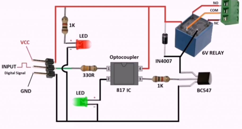
Also want to check if this sketch is using optocoupler correctly. I have no clue :(

Relay used https://sharvielectronics.com/product/spdt-5v-30a-relay-pcb-mount/

\$\endgroup\$
15
  • 1
    \$\begingroup\$ The nodeMCU looks like a 3.3V device rather then 5V. 3.3V is probably too low for both the optocoupler LED and the green LED in series. You can try bridging the green LED which should result in roughly 5mA trough the opto LED. \$\endgroup\$ Commented Jun 30, 2021 at 19:40
  • 2
    \$\begingroup\$ Please show your circuit. I don’t find any datasheet for it but coil needs in the order of 400 mW. How do you supply it? \$\endgroup\$
    – winny
    Commented Jun 30, 2021 at 20:34
  • \$\begingroup\$ @varun, if you edit the question there is a circuit schematic tool that you can use to draw an example circuit \$\endgroup\$
    – Voltage Spike
    Commented Jun 30, 2021 at 20:53
  • \$\begingroup\$ you can use a transistor (npn or nchan) to fix this. 5v- signal via 20k resistor. signal to tranny's drain/collector, tranny's source/emitter to gnd. Tranny's gate/base to nodeMCU pin. Note: the logic will be inverted HI/LO. \$\endgroup\$
    – dandavis
    Commented Jun 30, 2021 at 22:01
  • 1
    \$\begingroup\$ Where is Vcc coming from? Why the optocoupler? \$\endgroup\$
    – winny
    Commented Jul 1, 2021 at 6:43

2 Answers 2

1
\$\begingroup\$

Using an optocoupler due to "avoid any damage to microcontroller" is questionable. I see where you are coming from, but better start with something working and adding protections if needed (you won't).

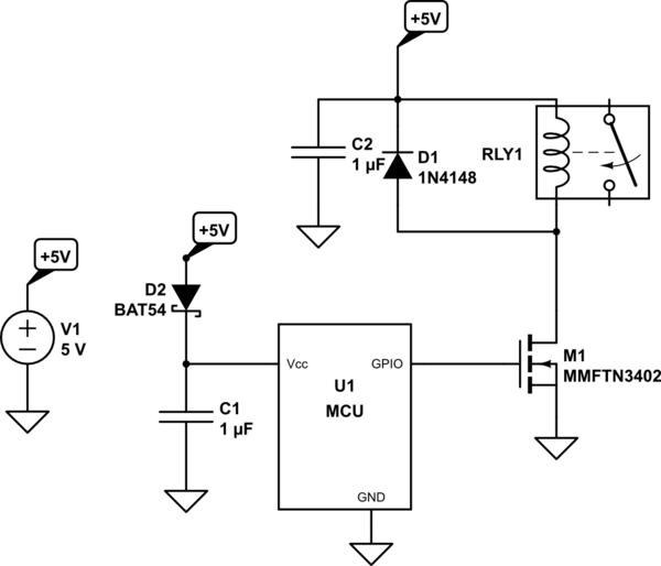
This is the most bog standard setup for triggering a relay from an MCU:

schematic

simulate this circuit – Schematic created using CircuitLab

D2 may be over the top, but sometimes it's a cheap way to get around with too low capacitance for non critical things like your relay while making sure you won't brown-out your MCU.

\$\endgroup\$
7
  • \$\begingroup\$ I dont have mosfet available will bc547b or 2n2222A work? Or if with some minor alterations my current circuit can work? Had created 2 of them dont want to redo everything :( \$\endgroup\$
    – Varun
    Commented Jul 2, 2021 at 12:46
  • \$\begingroup\$ Sure, ditch the optocoupler, calculate your base resistor to be within the limit of how much the MCU can source and that you are saturating it for your relay coil consumption. \$\endgroup\$
    – winny
    Commented Jul 2, 2021 at 12:55
  • \$\begingroup\$ Tried that even that didnt work for me with nodemcu... Works with 5v :( \$\endgroup\$
    – Varun
    Commented Jul 2, 2021 at 18:12
  • \$\begingroup\$ Ditch the MCU. Apply 5 V to the base resistor. Does it pull the relay? \$\endgroup\$
    – winny
    Commented Jul 2, 2021 at 18:19
  • \$\begingroup\$ Tried these nothing works with nodemcu :youtu.be/HXiL8p_sDZ8 drive.google.com/file/d/127OrtJif8SwfH3pJHJS8Kd-bYoOSEjfe/view \$\endgroup\$
    – Varun
    Commented Jul 3, 2021 at 7:36
1
\$\begingroup\$

Issue is 3.3V output from nodemcu. Added a level shifter and also removed with green LED as suggested by @Unimportant

\$\endgroup\$
1
  • 1
    \$\begingroup\$ Makes perfect sense. Thank you for adding the answer. \$\endgroup\$
    – winny
    Commented Jul 4, 2021 at 16:37

Your Answer

By clicking “Post Your Answer”, you agree to our terms of service and acknowledge you have read our privacy policy.

Not the answer you're looking for? Browse other questions tagged or ask your own question.