0
\$\begingroup\$

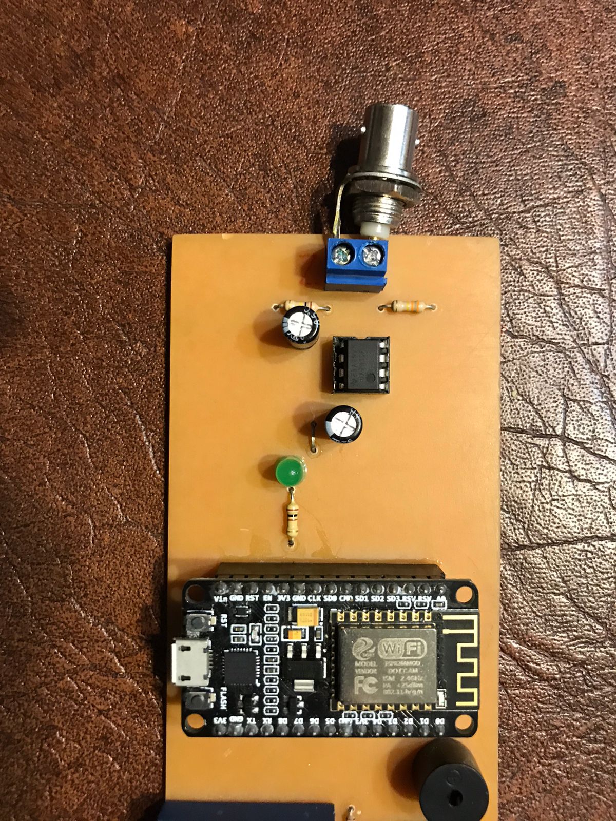
I am doing a hydroponics project at school. For this I need to make a circuit for a Ph sensor, I was going crazy looking and I found only one that did not really work for me, I will add photos. The voltages do not give me as they should give me Where I got the schematic from is here: Building a pH meter circuit - is it feasible? Abe Karplus did answer.
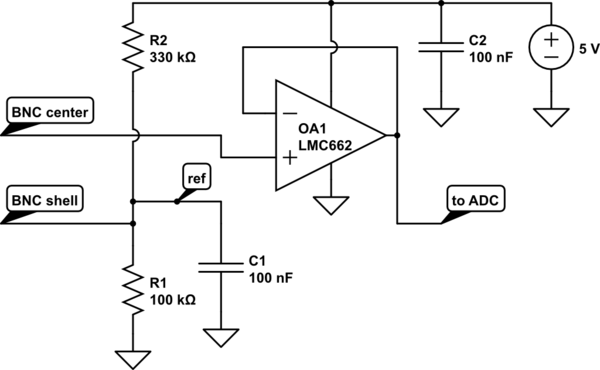
enter image description here By the way, I didn't use the op amp that this man used. I used a UA741CP.

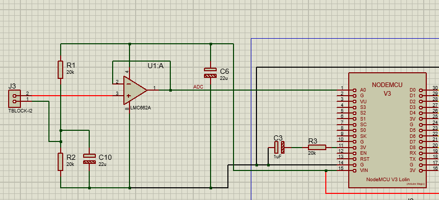
Then I used the same scheme that that man came up with to use in proteus and then make the board. enter image description here enter image description here
And this is how I got the board: enter image description here enter image description here

\$\endgroup\$
2
  • 5
    \$\begingroup\$ The 741 opamp will not work for this project. Its design is 53 years old and its datasheet shows only a 30V supply, but a few might work with a 10V supply. Its input bias current is 125 thousand times higher than the Cmos opamp in the original circuit. Its output does not go anywhere near ground or the positive supply. \$\endgroup\$
    – Audioguru
    Commented Oct 3, 2021 at 0:26
  • \$\begingroup\$ If you have limited access to components... Do you have a catalog of some sort of the components that are available? \$\endgroup\$
    – polwel
    Commented Oct 7, 2021 at 7:04

3 Answers 3

3
\$\begingroup\$

You need to use an opamp with low input bias current -- the LMC662 is suitable. Also a '741 doesn't have very good input or output common-mode voltage range and so may not work so well with just a 5 V supply.

since your board is laid out, a LMC662 won't fit in the same pinout. A TL071 or similar will however work. It is also available in an 8-pin PDIP package.

\$\endgroup\$
10
  • \$\begingroup\$ The minimum supply for a TL071 is 7V or 10V. Its inputs and output are not rail-to-rail. It is almost obsolete (the TL072 dual for stereo) is obsolete today. \$\endgroup\$
    – Audioguru
    Commented Oct 3, 2021 at 0:31
  • \$\begingroup\$ So should I or should I not use an LMC662? Is the pcb layout well connected? \$\endgroup\$ Commented Oct 3, 2021 at 1:35
  • \$\begingroup\$ The pcb is designed for a single opamp. The LM662 is a dual opamp that needs to have its unused opamp disabled and its positive pin is on a different pin than a single opamp. Find a single Cmos opamp. \$\endgroup\$
    – Audioguru
    Commented Oct 3, 2021 at 2:39
  • \$\begingroup\$ @Audioguru can you give me more information? i really need to fix this board, it's for a project in my school. I'm using a ESP8266 with the ADC pin, and now i'm confuse, i read that this circuit use positive and negative voltage, the ADC pin can't use negative voltage. It's true that my circuite use positive and negative voltage? \$\endgroup\$ Commented Oct 3, 2021 at 15:36
  • \$\begingroup\$ So I think that i have 2 problems, the amp op and the negative voltage. \$\endgroup\$ Commented Oct 3, 2021 at 15:37
1
\$\begingroup\$

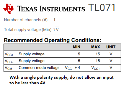
This is what Texas instruments say about their TL071 opamp:TL071

\$\endgroup\$
4
  • \$\begingroup\$ The datasheet actually says "Wide supply voltage: ±2.25", and most specs are guaranteed from 4.5 V, but I agree that another opamp could be better. \$\endgroup\$
    – jp314
    Commented Oct 4, 2021 at 18:15
  • \$\begingroup\$ So i have to change my opamp to TL071 and my circuit should work? \$\endgroup\$ Commented Oct 5, 2021 at 21:11
  • \$\begingroup\$ The new datasheet has two versions of the TL071 opamp. There is the older TL071 one that has a recommended minimum supply of 10V and a recommended input common mode voltage of+4V when there is no negative supply, and the new TL071H that has a recommended minimum supply of 4.5V and a recommended input common mode voltage of +2V when there is no negative supply. The old one is in many packages but the new one is in only surface mount packages. \$\endgroup\$
    – Audioguru
    Commented Oct 5, 2021 at 23:51
  • \$\begingroup\$ @Audiogurú and what is the problem if i use a LMC662 like the schematic say? It has 8 pins \$\endgroup\$ Commented Oct 6, 2021 at 11:49
0
\$\begingroup\$

Your pcb is designed for a single opamp. the dual opamp has different pin numbers for its + power supply and for the output of its first opamp. Also the second opamp in the dual opamp must be disabled. You must find a Cmos single opamp.

Here are the differences in their pins: opamps

\$\endgroup\$
2
  • \$\begingroup\$ Ok so i will use the TL071. i hope it works \$\endgroup\$ Commented Oct 7, 2021 at 20:47
  • \$\begingroup\$ didn't work. I change to the TL071 and i replace the 330K to 100K \$\endgroup\$ Commented Oct 19, 2021 at 0:03

Your Answer

By clicking “Post Your Answer”, you agree to our terms of service and acknowledge you have read our privacy policy.

Not the answer you're looking for? Browse other questions tagged or ask your own question.