0
\$\begingroup\$

I’m trying to choose/work out if I need capacitors for the input and output of two DC/DC converters.

The first converter is a Murata PAE-29/3-D48, powering this along a ~30cm cable, and a bike headlight, using ~100ma with a ~40cm cable.

The second is a Mornsun VCB4805SBO-30WR3 (5v version), powering a wireless phone charger which uses ~1.3A with a ~60cm cable.

Both will be powered by a 48v lithium battery pack, on a bike which will be used in weather from -5 to 25 C.

My main point of confusion is the capacitor ripple current rating - I’m aware I should aim for it not to be exceeded, but both DC/DC datasheets only list ripple voltage and I don’t know how to calculate the current (or the frequency for that matter). The datasheets also mention choosing a low ESR capacitor, but I don’t know what counts as ‘low’, or why many capacitors don’t seem to list an ESR rating at all.

Finally, neither datasheet seems to mandate the use of input or output capacitors, and I’m not sure how to know whether they’re needed.

Thanks!

\$\endgroup\$

2 Answers 2

1
\$\begingroup\$

You choose to use DCDC converter modules, that is a wise choice because most of the critical decoupling capacitors will be on the module already.

From the datasheets I deduct that only if you need to reduce the ripple even more, that then you could add (low ESR) capacitors, up to the value mentioned in the datasheet.

So don't over worry about ripple on the output voltages of DCDC converters. Most devices can handle some ripple.

I would not expect a bike headlight to be that sensitive to ripple so for the headlight's DCDC converter, just try it with no additional capacitors at the output at all. Adding a 100 uF ("standard", doesn't need to be low ESR) directly at the input of the DCDC is good practice.

The phone is normally charged from a wall charger and they will also have some ripple. That is to be expected. So I also expect that to charge your phone you don't need additional (low ESR) capacitors. But again adding a 100 uF ("standard", doesn't need to be low ESR) directly at the input of the DCDC is good practice.

My main point of confusion is the capacitor ripple current rating

I would not worry about that as most of the ripple suppression is done on the module already. If with such a DCDC module the ESR and current rating of the external capacitors was so critical then that should be mentioned in the datasheet. But also, you choose a module so that you're not bothered by such things as they should be taken care of on the module.

\$\endgroup\$
0
0
\$\begingroup\$

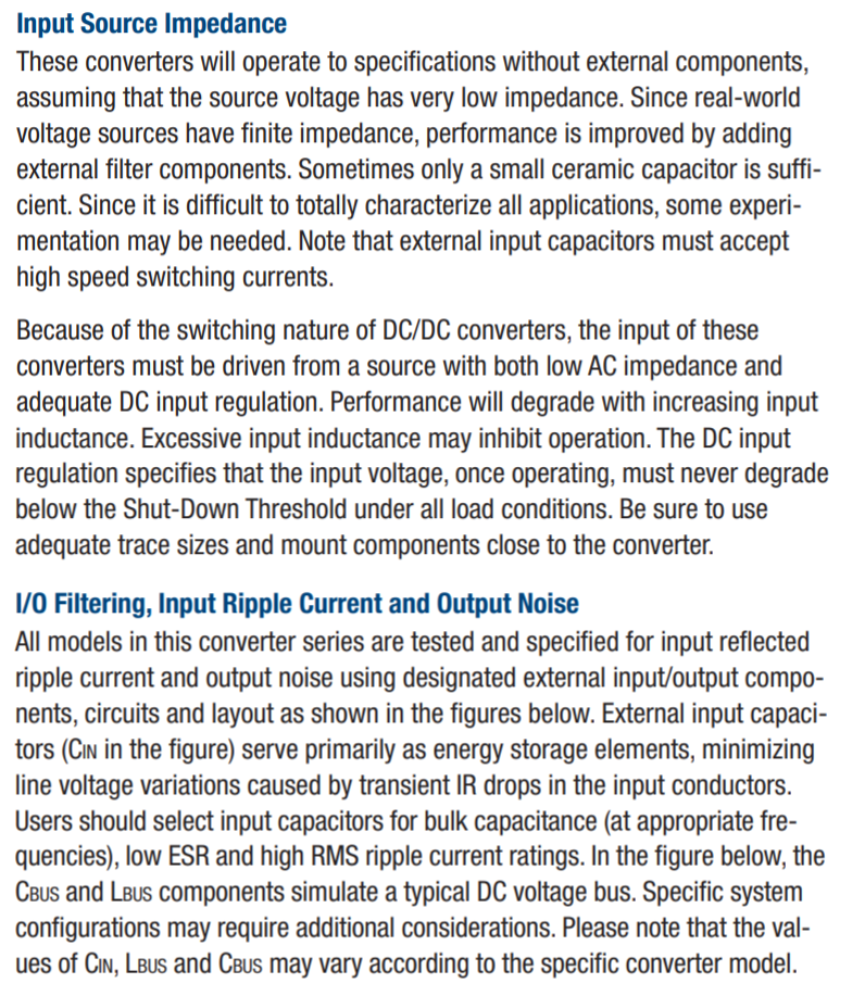
neither datasheet seems to mandate the use of input or output capacitors, and I’m not sure how to know whether they’re needed.

Try reading page 14 of the murata data sheet: -

enter image description here

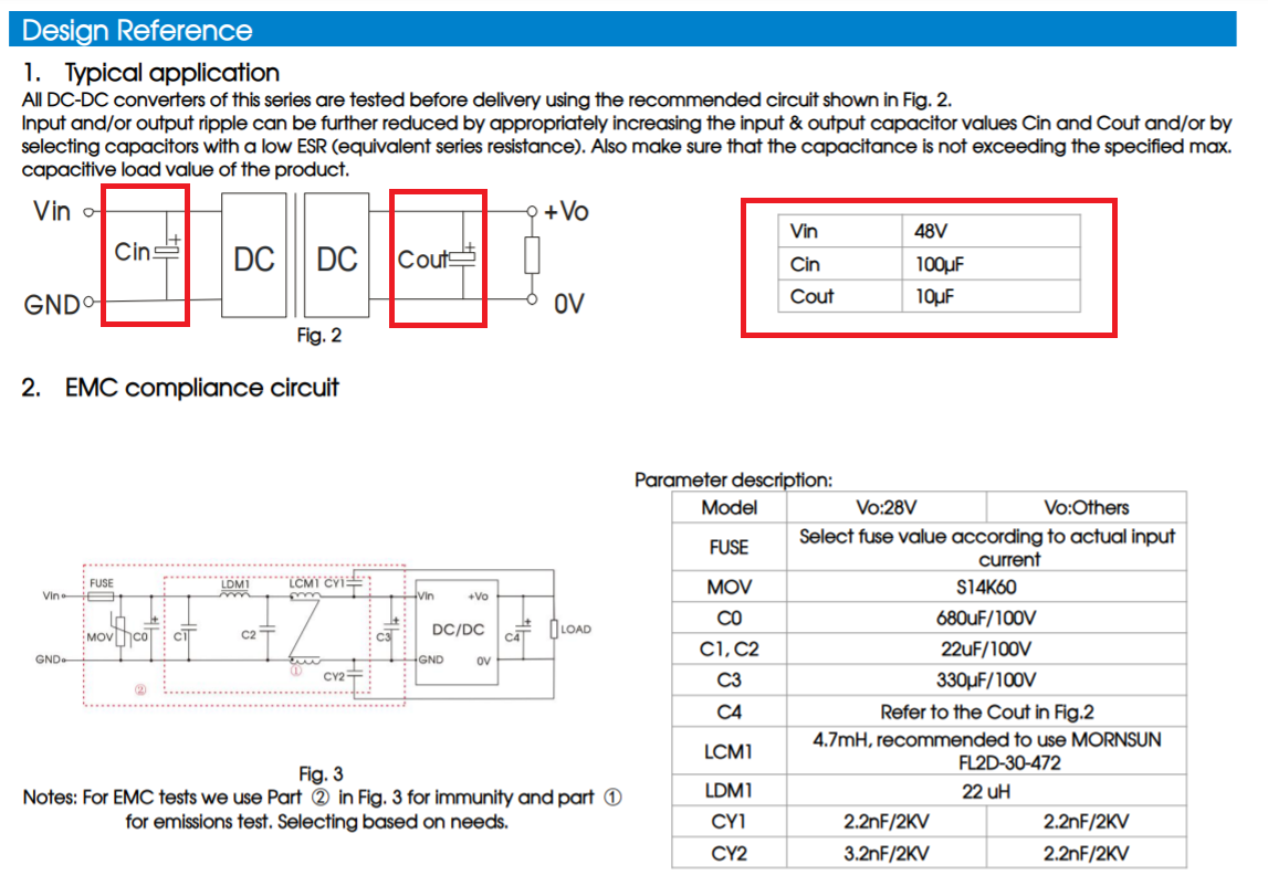
You will probably need to add input capacitors but, to what extent is governed by external wiring inductance. May I suggest you opt for 100 uF bulk capacitance and 1 μF ceramic in parallel close the module. This will provide a half-decent combination of high-ish bulk capacitance and low ESR.

You will probably need to do something similar for the other module too: -

enter image description here

\$\endgroup\$
6
  • \$\begingroup\$ Thanks for your answer! I did read these parts of the datasheets, but they only specified the capacitance values and were otherwise seemed vague: 'low-ESR', 'high RMS ripple current ratings' and 'appropriate frequencies'. They also state 'typical application' and 'assuming the source voltage has very low impedance' so I wasn't sure if they were even necessary. I perhaps should have mentioned in the post that I know very little about electronics! So I still wouldn't know how to choose a capacitor for either module re: ripple current rating or ESR (what counts as 'low'?) \$\endgroup\$
    – Tpw
    Commented Nov 11, 2021 at 12:24
  • \$\begingroup\$ Use the values and types I gave in my answer I.e. 100 uF (electrolytic for example) and a 1 uF ceramic. Both need to be voltage rated about double your incoming supply voltage maximum. \$\endgroup\$
    – Andy aka
    Commented Nov 11, 2021 at 12:30
  • \$\begingroup\$ Presumably the higher the ripple current ratings the better? And the same combination for the output (for the second module at least)? \$\endgroup\$
    – Tpw
    Commented Nov 11, 2021 at 12:40
  • \$\begingroup\$ @tpw use a 100 uF radial electrolytic with adequate voltage rating to supply the main DC current and use a 1 uF ceramic X7R for the ripple artefacts. Your situation isn't sufficiently described to work out wire inductance but, the values I gave should be a good start. \$\endgroup\$
    – Andy aka
    Commented Nov 11, 2021 at 12:50
  • \$\begingroup\$ @Tpw if you are done now you should close this session down by accepting one of the answers. I think you may not have been aware of that. Read this to understand why and how. \$\endgroup\$
    – Andy aka
    Commented Nov 11, 2021 at 14:13

Your Answer

By clicking “Post Your Answer”, you agree to our terms of service and acknowledge you have read our privacy policy.

Not the answer you're looking for? Browse other questions tagged or ask your own question.