0
\$\begingroup\$

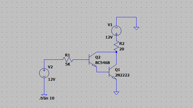
I want to increase the first transistor collector current but I can't. I increase the first transistor base current. Transistor doesn't respond as I expected. Collector current doesn't increase.

When I decrease the base current, the beta value increases.

Why does the transistor response this way? Can you explain?

enter image description here

enter image description here

\$\endgroup\$
4
  • \$\begingroup\$ 12V/5k = 2.4mA, enough to saturate, beta is not relevant in saturation. Q2 collector current only needs to be enough to exceed Q1's base requirement. What is actually happening? Telling us it's not what you expect tells us a little about what you expect, but not as much as if you actually told us what you expect, and of course, what you are actually trying to do. \$\endgroup\$
    – Neil_UK
    Commented Dec 9, 2021 at 9:24
  • \$\begingroup\$ I want to increase the collector current of the first transistor up to 50mA, why can't I? \$\endgroup\$ Commented Dec 9, 2021 at 10:34
  • \$\begingroup\$ At first you should inform us about the background of your question. What do you want? Linear operation (amplification) or operation as an on/off circuit (saturation)? \$\endgroup\$
    – LvW
    Commented Dec 9, 2021 at 10:51
  • \$\begingroup\$ For a load current of 500mA, it should work at saturation, actually the system is working, I'm just wondering. \$\endgroup\$ Commented Dec 9, 2021 at 11:00

1 Answer 1

2
\$\begingroup\$

I want to increase the collector current of the first transistor up to 50mA, why can't I?

Because the emitter current of Q2 the sum of its base and collector currents. The Q2 emitter current flows into Q1 base, which turns it on.

Q1, if turned on hard, into saturation, could have a VCE of a few hundred milivolts. That is, it could reverse bias Q2. Therefore Q1 doesn't saturate. It turns on just enough to reduce the current through Q2 to what it needs to stay turned on.

If you increased the base current in Q2 once Q1 was conducting, then paradoxically I'd expect the collector current to reduce. The increased base current would flow out of the emitter, turning Q1 on harder, which would reduce VCE and therefore collector current.

If somehow magically Q2 collector current went up to 50 mA, Q1 would turn on fully. With a VCE of (say) 400 mV and a VBE of at least 700 mV, Q2 would be reverse biassed, and collector and emitter currents would reverse.

\$\endgroup\$
8
  • \$\begingroup\$ I never thought of it this way.Thanks a lot. \$\endgroup\$ Commented Dec 9, 2021 at 11:49
  • \$\begingroup\$ @bahadırgüven Glad to help. I've just clarified my answer to refer to only the case of a Darlington where the second transistor has turned on, ie your question. If the second transistor is off, then I'd expect increased base current to increase the collector current in the first transistor. \$\endgroup\$
    – Neil_UK
    Commented Dec 9, 2021 at 11:54
  • \$\begingroup\$ I think reverse active region is forming, right? collector current is negative when R1i is 100 ohms in lt spice. \$\endgroup\$ Commented Dec 9, 2021 at 12:23
  • \$\begingroup\$ @bahadırgüven R1 = 100 ohms gives enough current to saturate Q1, via Q2's BE junction, all by itself. So no collector current is needed in Q2, and Q1 will saturate and pull current out of Q2's collector. \$\endgroup\$
    – Neil_UK
    Commented Dec 9, 2021 at 12:32
  • \$\begingroup\$ I don't understand, can you explain a little more? \$\endgroup\$ Commented Dec 9, 2021 at 16:43

Your Answer

By clicking “Post Your Answer”, you agree to our terms of service and acknowledge you have read our privacy policy.

Not the answer you're looking for? Browse other questions tagged or ask your own question.