I am using digital IR Receiver Module and digital IR Transmitter Module connected each with different Arduino Uno. How can I transmit data like "1234" to the receiver and display data on LCD? This is because most of the example that I found using IR remote code like Sony and RC4. I just want to send a simple data.
1 Answer
As the question does not state which digital IR Transmitter and Receiver modules are in use, this answer explains how infrared data communication can be achieved using simply a generic IR LED, and a modulated IR receiver such as Vishay's TSOP17xx or other similar parts.
Assumptions:
- IR LED chosen can be driven with 20 mA current, e.g. IR333
- TSOP1756 sensor is to be used (56 KHz modulation).
- Change modulation frequency according to actual part used in sensor module. For TSOP11 38, for instance, modulation frequency is 38 KHz.
Receiving:
This is the easy part. Simply connect the OUT pin of the sensor to the serial RX pin of your Arduino (digital Pin 0). If your Arduino is one of the basic (older) models, use Serial.read() in loop():
int inputByte = 0;
if (Serial.available() > 0) {
    // read the incoming byte:
    inputByte = Serial.read();
    // Do stuff with this byte, then loop again
For the Arduino Mega or Due, you can also use Serial1, Serial2 or Serial3, depending on which RX pin you use.
For additional reference, see the Arduino Serial reference.
N.B. Power the sensor with the same voltage as your Arduino actually runs its microcontroller at, either 3.3 or 5 Volts depending on Arduino model. Each Arduino board has a suitable voltage output pin you can use for this. Do not use the external supply (7 to 12 Volts typically) provided to the Arduino board.
Transmitting:
You have two options: (1) Arduino, LED and passive components, or (2) using an additional logic gate component. The first option is good for low-current IR LEDs (20-30 mA tops):
- Set one of the Arduino timers (Timer1 for instance, it is a 16-bit timer) for the modulation frequency, with output to one of the timer pins D9 or D10 associated with this timer.
- For a 16 MHz Arduino, to get approximately 56 KHz, use a counter overflow value of 286 ( =
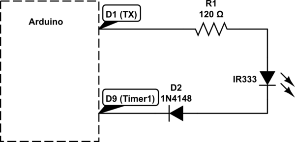
55,944 Hz). An overflow value of 421 will deliver38,005 Hzinstead, if needed. Connect a suitable current limiting resistor (120 to 150 Ohms on a 5 Volt Arduino = approximately 18 mA to 23 mA limit), a small signal diode, and the LED in series as shown below:

simulate this circuit – Schematic created using CircuitLab
- When the TX pin is high, the LED will be pulsed at the modulation frequency. When TX pin is low, the LED will not light up, and the small-signal diode in series will protect the LED from reverse breakdown.
- If your Arduino is the 3.3 Volt type, then the small-signal diode is not really essential.
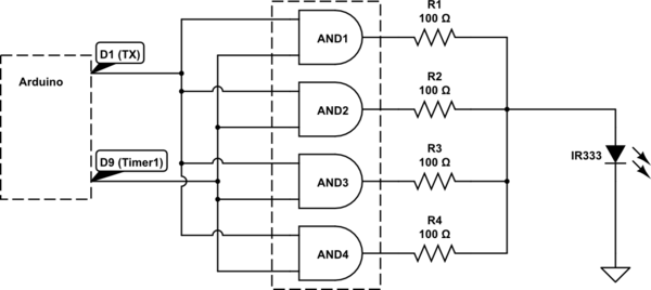
For driving a higher current LED, an additional logic component, a quad AND gate such as SN74AS1008 can be used. This part sources or sinks up to 48 mA per gate, and multiple gates can be paralleled for higher current drive.
- Connect the Timer1 output as set up above, to one input of each of the AND gates.
- Connect the TX output as mentioned above, to the second input of each of the AND gates.
- Connect a current limiting resistor of suitable value to each output pin of these 4 AND gates - such that the sum of the 4 output currents equals the desired drive current on the LED
- Connect the other ends of the 4 current limiting resistors to the Anode of the LED, with the Cathode connected to Arduino ground.
- You may have to supply the AND gate's Vcc from an external (5 Volts) power supply, since the Arduino's on-board regulator will overheat if too much current is drawn through it. Make sure the ground of this external supply is connected to Arduino GND.

Now simply use Serial.write() in your Arduino loop() code, to transmit any serial data, which will be received by the Serial.read() at the other end, as described previously.
