0
\$\begingroup\$

I have been trying to interface a bipolar stepper motor with an ATmega32 controller using AVR assembly, but it just keeps clicking without movement or just move back and forth in the same step. Here is the code:

    .include "m32def.inc"

    ; define motor pins         
    .equ A1              = PB0
    .equ A2              = PB1
    .equ B1              = PB2
    .equ B2              = PB3


    .cseg                       
    .org 0x00


     ser r16       
     out DDRB, r16          ;do not need to save r16


start:

     ; Step 1

     sbi PORTB, A1
     cbi PORTB, A2
     cbi PORTB, B1
     cbi PORTB, B2
     ldi delayMultiplier, 50
     rcall delay


     ; Step 2
     cbi PORTB, A1
     cbi PORTB, A2
     sbi PORTB, B1
     cbi PORTB, B2
     ldi delayMultiplier, 50
     rcall delay
     
     ; Step 3
     cbi PORTB, A1
     sbi PORTB, A2
     cbi PORTB, B1
     cbi PORTB, B2
     ldi delayMultiplier, 50
     rcall delay


     ; Step 4
     cbi PORTB, A1
     cbi PORTB, A2
     cbi PORTB, B1
     sbi PORTB, B2

      
     ldi delayMultiplier, 50
     rcall delay
     rjmp start


    .def delayMultiplier = r25

    .equ l1      = 20000


 delay:
      push r27
      push r26
      push r25


 loop2:
    
      ldi r26, LOW(l1)
      ldi r27, HIGH(l1)
      
loop1:
      sbiw r26, 1
      brne loop1

      dec delayMultiplier
      brne loop2

      
      pop r25
      pop r26
      pop r27


      ret

I tried some C code that does the same function and it kind of worked, but was still glitchy and behaved weirdly. It starts rotating then begin clicking a bit and eventually totally stopping.

 #include <avr/io.h>
    #define F_CPU 8000000L
    #include <util/delay.h>


    int main(void)
    {
        DDRB = 0xff;
        
        while (1) 
        {
            
         PORTB = 0x01;  //A1 high
         _delay_ms(500);
         PORTB = 0x02;  //B1 high
         _delay_ms(500);
         PORTB = 0x04;  //A2 high
         _delay_ms(500);
         PORTB = 0x08;  //B2 high
         _delay_ms(500);


        }
    }

lastly I tried it using an Arduino UNO, and for some reason is worked flawlessly

void setup() {
  // put your setup code here, to run once:
DDRB = 0xff;
}

void loop() {
  // put your main code here, to run repeatedly:

    PORTB = 0x01;  //A1 high
    delay(500);
    PORTB = 0x02;  //B1 high
    delay(500);
    PORTB = 0x04;  //A2 high
    delay(500);
    PORTB = 0x08;  //B2 high
    delay(500);

} 

it also worked with this code

int a1 = 7, a2 = 6, b1 = 5, b2 = 4;


void setup() {
  // put your setup code here, to run once:
pinMode(a1,OUTPUT);
pinMode(a2,OUTPUT);
pinMode(b1,OUTPUT);
pinMode(b2,OUTPUT);
}

void loop() {
  // put your main code here, to run repeatedly:
digitalWrite(a1,HIGH);
digitalWrite(a2,LOW);
digitalWrite(b1,LOW);
digitalWrite(b2,LOW);

delay(100);

digitalWrite(a1,LOW);
digitalWrite(a2,LOW);
digitalWrite(b1,HIGH);
digitalWrite(b2,LOW);

delay(100);

digitalWrite(a1,LOW);
digitalWrite(a2,HIGH);
digitalWrite(b1,LOW);
digitalWrite(b2,LOW);

delay(100);

digitalWrite(a1,LOW);
digitalWrite(a2,LOW);
digitalWrite(b1,LOW);
digitalWrite(b2,HIGH);

delay(100);


}

Obviously I have no Idea what is going on so please advice.

Note that I am doing this for a university project so I have to do it using assembly.

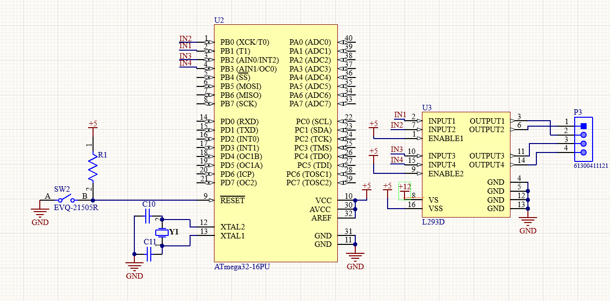
Circuit Schematic:

enter image description here

\$\endgroup\$
2
  • \$\begingroup\$ Can you verify the supply voltages applied to the output with some explanation of sequence. ( This is sooo primitive, please get the Gcode for Arduino and CNC shield with Gcode Panel open software for windows. \$\endgroup\$
    – D.A.S.
    Commented Dec 30, 2021 at 2:49
  • \$\begingroup\$ I did remove the stepper and connected LEDs instead to confirm the sequence is okay, also I measured the voltage at each output with the stepper removed and all is ok. I know this primitive and basically useless code, but as I mentioned this is for a University project so it has to be done this way unfortunately. \$\endgroup\$
    – Seif_1999
    Commented Dec 30, 2021 at 2:57

2 Answers 2

0
\$\begingroup\$

You seem to have inconsistent pins, PORTs, and DDRs.

Your schematic seems to show the motor controller connected to chip PD0-3, but your working Arduino code sample seems to access PORTB. Then the second working Arduino code is accessing the PORTD pins (using their Arduino pin numbers).

Your non-working C code example seems to set the DDRD but then update the PORTB bits.

Lots of sloppy inconsistencies here, which will make it very hard to figure out what is happening.

Are you using the same hardware in all these examples?

I also see that in your schematic you are using PORTD pins that are also multiplexed with the serial port. If the serial port pins are enabled then the GPIO on this same pins is disabled. You do not show enabling the serial port in your ASM code, but again with everything so inconsistent it is hard to tell.

Clean everything up and report back with your results and I'm sure we can get everything working.

\$\endgroup\$
5
  • \$\begingroup\$ Okay, I will clean it up, try it again and report back. Thanks. Should I remove this question and post a new cleaned up one? \$\endgroup\$
    – Seif_1999
    Commented Dec 30, 2021 at 3:03
  • \$\begingroup\$ You can edit the current question. Also, looking at your ASM further it seems to functionally be completely different than the working Arduino code. It sets two PORT bits on each step whereas the Arduino code only sets one. I bet once you clean things up the answer will be clear. For me, cleaning up my own questions so I can post them on stack exchange often solves my problem. :) \$\endgroup\$
    – bigjosh
    Commented Dec 30, 2021 at 3:06
  • \$\begingroup\$ I just edited the question, please have look a look and let me know what you think. And yes indeed it was a mess :), sorry for that, I had so many tries that I got codes mixed up. Anyway, I cleaned up every thing tried it again, but got the same results. I moved away from PORTD to avoid any conflict with serial (even though I did not enable it) and used the same steps sequence in asm, C, and arduino. \$\endgroup\$
    – Seif_1999
    Commented Dec 30, 2021 at 3:38
  • \$\begingroup\$ @Seif_1999 I do not trust that your first Arduino example can possibly work as claimed since it never sets the DDR register. If the code in the question does not match the code you are running then no way someone looking at the question can help you! I'd take a step back and start from the simplest example that you can get working and then take small and controlled steps forward from that example to your final goal, testing and confirming at each step. If you do this carefully then I think you will be much better off. Randomly changing stuff in different places and hoping never works! :) \$\endgroup\$
    – bigjosh
    Commented Dec 30, 2021 at 3:45
  • \$\begingroup\$ You are absolutely right, that's my bad. But if can have a look on the second one it did work. Sadly this is the simplest example I can start with. I am just trying to get the motor to rotate consistently in one direction and I can not even do that. \$\endgroup\$
    – Seif_1999
    Commented Dec 30, 2021 at 3:51
0
\$\begingroup\$

The assembly code can't use rcall to subroutine because the stack is not initialized. It also does not adhere to standard startup code with interrupt vectors, including a reset vector, at address 0, but it may not require that. Please see the datasheet or application notes for working examples of assembly code.

\$\endgroup\$

Your Answer

By clicking “Post Your Answer”, you agree to our terms of service and acknowledge you have read our privacy policy.

Not the answer you're looking for? Browse other questions tagged or ask your own question.