1
\$\begingroup\$

I have a tricky situation, that when a fault is detected by one of two safety uC, the system needs to be shut down and also the power supply, that powers the system. A restart can be triggered from the outside by a additional SBC.

So here is a schematic, that describes the system on a high level:
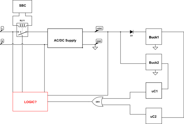
schematic

simulate this circuit – Schematic created using CircuitLab

At startup, the SBC gives a puls (1s maybe) that should trigger a relay (can also be in this logic board), this should activate the power supply and the relay for L should be self retaining from the logic after startup. There are two circuits with uC powerered from two independent buck converter and if one uC detects a fault, the system should turn off by triggering somehow this relay at the input (it might be 2 relays, since no single point of failure and also the OR gate below should be somehow two independent optocouplers).

The logic should be fully in hardware and no uC can be used. Any ideas on how to achieve that?

Edit: One thing that came to my mind is the following circuit, but I don't like the single logic from the SBC:

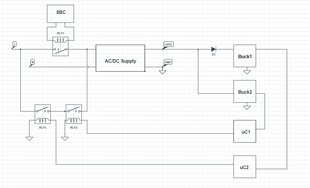
enter image description here

\$\endgroup\$
3
  • \$\begingroup\$ Your ac/dc supply is a single point of failure. I’d suggest a watchdog circuit from the microcontrollers - the micros have to send a stream of pulses to keep the watchdog happy. You’ll also need some test circuitry - firstly to ensure safety, secondly, when it does fail that you’ll be able to diagnose the fault. The system should tolerate one failure, but all failures must be detected. \$\endgroup\$
    – Kartman
    Commented Jan 26, 2022 at 13:52
  • 1
    \$\begingroup\$ You are right, the ac/dc supply is a single point of failure, but not critical, since power loss makes the system save and overvoltage etc. will also trigger the uC to shut down the system. So the PSU needs no redundency. The fault is send over a CAN bus to the SBC with additional keep alives from both uC. The SBC itself can also shut down the system (needs an aditional relay on the neutral) in case to keep alive or error state arrives \$\endgroup\$ Commented Jan 26, 2022 at 14:00
  • \$\begingroup\$ Useful search term : NVR switch. A common industrial component. \$\endgroup\$
    – user16324
    Commented Jan 26, 2022 at 15:17

2 Answers 2

1
\$\begingroup\$

The logic should be fully in hardware and no uC can be used. Any ideas on how to achieve that?

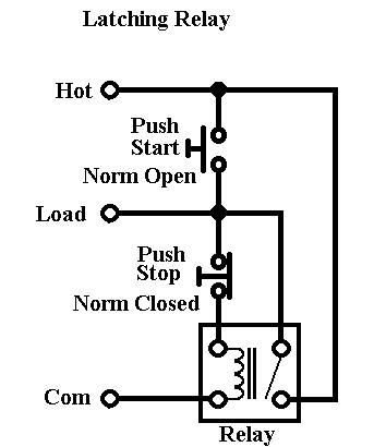
It seems to me that you can draw-on the standard latching on/off control circuit used to power AC motors. They use a push-button to activate the motor via a relay and, a spare contact on the relay provides the latching function that your SBC (whatever that is) requires. The stop button interrupts the latching contact and the motor turns off: -

enter image description here

Image from here.

So, if your two microcontrollers could activate another relay that replaced the stop contact, I think you'd be good to go. You could probably use an opto-device that replaced the stop switch also (saving cost and space).

\$\endgroup\$
2
  • \$\begingroup\$ Thank you, yes that looks like a good idea. I had 3 relays in my edit, but the idea with optocoupler can be good too. Probably a second relay for the SBC (single board computer) would also be good and probably another co-processor for the SBC to prevent single point of failure. \$\endgroup\$ Commented Jan 26, 2022 at 13:32
  • \$\begingroup\$ @HansPeterLoft if you are done here then please accept one of the answers. \$\endgroup\$
    – Andy aka
    Commented Feb 22, 2022 at 9:44
1
\$\begingroup\$

I am not a safety expert but I know enough to know safety is hard.

You could use a simple latching relay with SET (SBC) and RESET (uC) to turn on power and then remove it with an alarm signal. But what if one of the uCs is destroyed by a sudden power surge? What if someone accidentally cuts an alarm wire? There is a whole category of products called safety relays that solve these problems to cut off power in alarm situations.

Some observations:

  • You should never use an on-state to trigger a safety cutoff. The alarm should be indicated by a LOSS of a signal. This way if a wire is cut or safety uC burns out your alarm will immediately trigger.
  • This also means you should have an AND logic to make sure all safety uCs agree that the system is healty
  • The safety uCs should be powered from somewhere which is not behind (this) cutoff switch so that they can provide an OK signal
  • The relay should not be allowed to be connected again if an alarm condition still exists

Safety relays address many of these issues "out of the box". They are also expensive but for a reason.

\$\endgroup\$
1
  • 1
    \$\begingroup\$ Hi Vaizki, yes that makes absolutely sense. Two relays as in my edit should do the trick, since they need to have both uC to stay logic high to have the system operational. Also the connection is then only possible, if the SBC wants to re-run the system. The problem with a safety relay is the extremly high price (100$ and above) \$\endgroup\$ Commented Jan 26, 2022 at 13:50

Your Answer

By clicking “Post Your Answer”, you agree to our terms of service and acknowledge you have read our privacy policy.

Not the answer you're looking for? Browse other questions tagged or ask your own question.