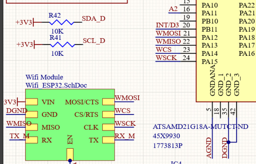
I've been attempting to use SERCOM2 SPI Master on the SAMD21G18J but have been unsuccessful. I tried the configurations with SERCOM0 and SERCOM4, and they both worked. The most intriguing behavior is that when I initialize the SERCOM2 SPI, all of the other I/O pins stop working as well. The clock is not generated, and CS is not operational.
I tried several bootloaders, but the results were the same. To begin, I used the bootloader of an Arduino Nano IOT 33, which uses the same chip, in order to use the Arduino IDE more easily.
Then, I tested with the bootloaders Arduino Zero and Adafruit M0 bootloader. The idea of testing other bootloaders was because the Arduino Nano IOT 33 uses SPI SERCOM2 to communicate with its WIFI module, and could be protected somehow. Any insight will be useful.
The schematic is displayed below:

Main routine:
// include the SPI library:
#include <SPI.h>
#include "SercomSPISlave.h"

SercomSPIMaster Spi2;

void setup() {
  PORT->Group[PORTA].DIR.reg |= PORT_PA08; // Output set wifi ctrl
  PORT->Group[PORTA].OUT.reg &= ~PORT_PA08;  // Turn OFF wifi
  // PORT->Group[PORTA].OUTCLR.reg |= PORT_PA08;

  PORT->Group[PORTA].DIR.reg |= PORT_PA04;  // set output Group; Turn-On Circuit;
  PORT->Group[PORTA].OUT.reg |= PORT_PA04;
  PORT->Group[PORTA].OUTSET.reg |= PORT_PA04; // Turn ON

  PORT->Group[PORTA].DIR.reg |= PORT_PA14;  // set CS output

  pinMode(4, OUTPUT);

  // set the slaveSelectPin as an output:
  pinMode (slaveSelectPin, OUTPUT); //spi1
  // initialize SPI:
  Spi2.Sercom2Masterinit(); //spi2
}

void loop() {
  char c = 'z', r;
  PORT->Group[PORTA].OUT.reg &= ~PORT_PA14;  // Turn OFF wifi

  delay(100);
  // send in the address and value via SPI:
  r = Spi2.transfer2(c); //spi1
  Serial.println(r);

  delay(100);

  // take the SS pin high to de-select the chip:
  PORT->Group[PORTA].OUTSET.reg |= PORT_PA14; // Turn ON; unset pin

  //delay(1000);
}
Header file:
     while (GCLK->STATUS.reg & GCLK_STATUS_SYNCBUSY); //Wait for synchronisation

  //Set up SPI Control A Register
  SERCOM2->SPI.CTRLA.bit.DORD = 0; //MSB first
  SERCOM2->SPI.CTRLA.bit.CPOL = 0; //SCK is low when idle, leading edge is rising edge
  SERCOM2->SPI.CTRLA.bit.CPHA = 0; //data sampled on leading sck edge and changed on a trailing sck edge
  SERCOM2->SPI.CTRLA.bit.FORM = 0x0; //Frame format = SPI

  // Choose PAD configuration
  SERCOM1->SPI.CTRLA.bit.DIPO = 0x1; //DATA PAD1 MISO is used as Master input (slave mode) // page 492
  SERCOM1->SPI.CTRLA.bit.DOPO = 0x3; //DATA PAD0 MOSI is used as Master output and PAD3 as SCK

  SERCOM2->SPI.CTRLA.bit.MODE = 0x3; //SPI in Master mode
  SERCOM2->SPI.CTRLA.bit.IBON = 0x1; //Buffer Overflow notification
  SERCOM2->SPI.CTRLA.bit.RUNSTDBY = 1; //wake on receiver complete

  //Set up SPI control B register
  SERCOM2->SPI.CTRLB.bit.RXEN = 0x1; //Enable Receiver
  //SERCOM2->SPI.CTRLB.bit.SSDE = 0x1; //Slave Selecte Detection Enabled
  SERCOM2->SPI.CTRLB.bit.CHSIZE = 0; //character size 8 Bit

  //SERCOM1->SPI.CTRLB.bit.PLOADEN = 0x1; //Enable Preload Data Register
  //while (SERCOM1->SPI.SYNCBUSY.bit.CTRLB);

  //Set Baud rate
  uint16_t BAUD_REG = ((float)SPI_CLK_FREQ / (float)(2 * SPI_BAUD)) - 1;  //Calculate BAUD value For Sync
  SERCOM2->SPI.BAUD.reg = SERCOM_SPI_BAUD_BAUD(BAUD_REG);       //Set the SPI baud rate
  SERCOM2->SPI.CTRLA.reg |= SERCOM_SPI_CTRLA_ENABLE;         //Enable the Sercom SPI
  while (SERCOM2->SPI.SYNCBUSY.bit.ENABLE);

  //Enable SPI
  SERCOM2->SPI.CTRLA.bit.ENABLE = 1;
  while (SERCOM2->SPI.SYNCBUSY.bit.ENABLE);
  SERCOM2->SPI.CTRLB.bit.RXEN = 0x1; //Enable Receiver, this is done here due to errate issue
  while (SERCOM2->SPI.SYNCBUSY.bit.CTRLB); //wait until receiver is enabled
};

uint8_t SercomSPIMaster::transfer2(uint8_t data) {
  while(SERCOM2->SPI.INTFLAG.bit.DRE == 0);
  SERCOM2->SPI.DATA.reg = data;
  while(SERCOM2->SPI.INTFLAG.bit.RXC == 0);
  return (uint8_t)SERCOM2->SPI.DATA.reg;
}

