I was looking for a dummy battery to power my Nikon D5200 so I can use it for streaming purposes or improved webcam for meetings. There are lots of options like this one but then I realized...
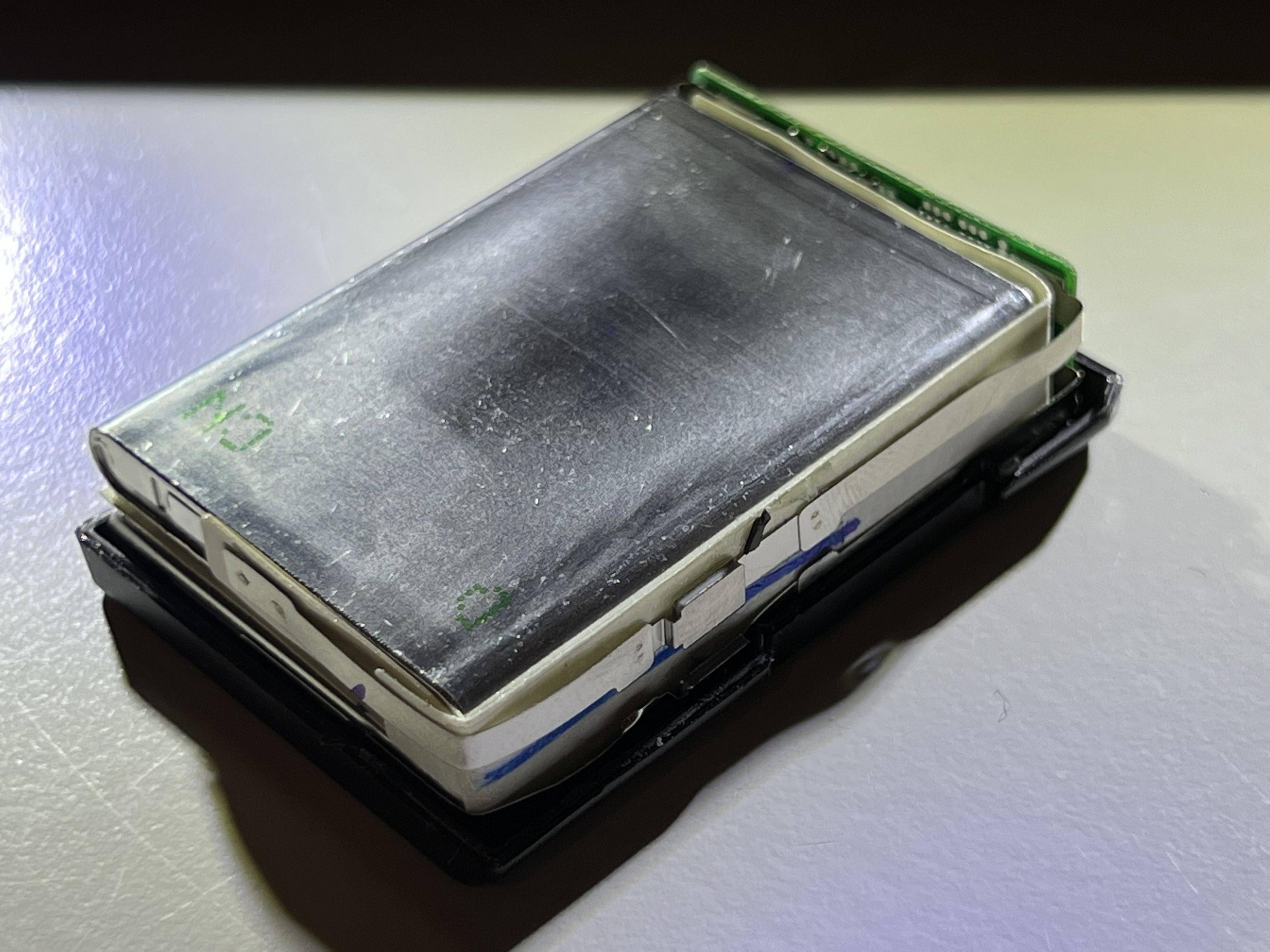
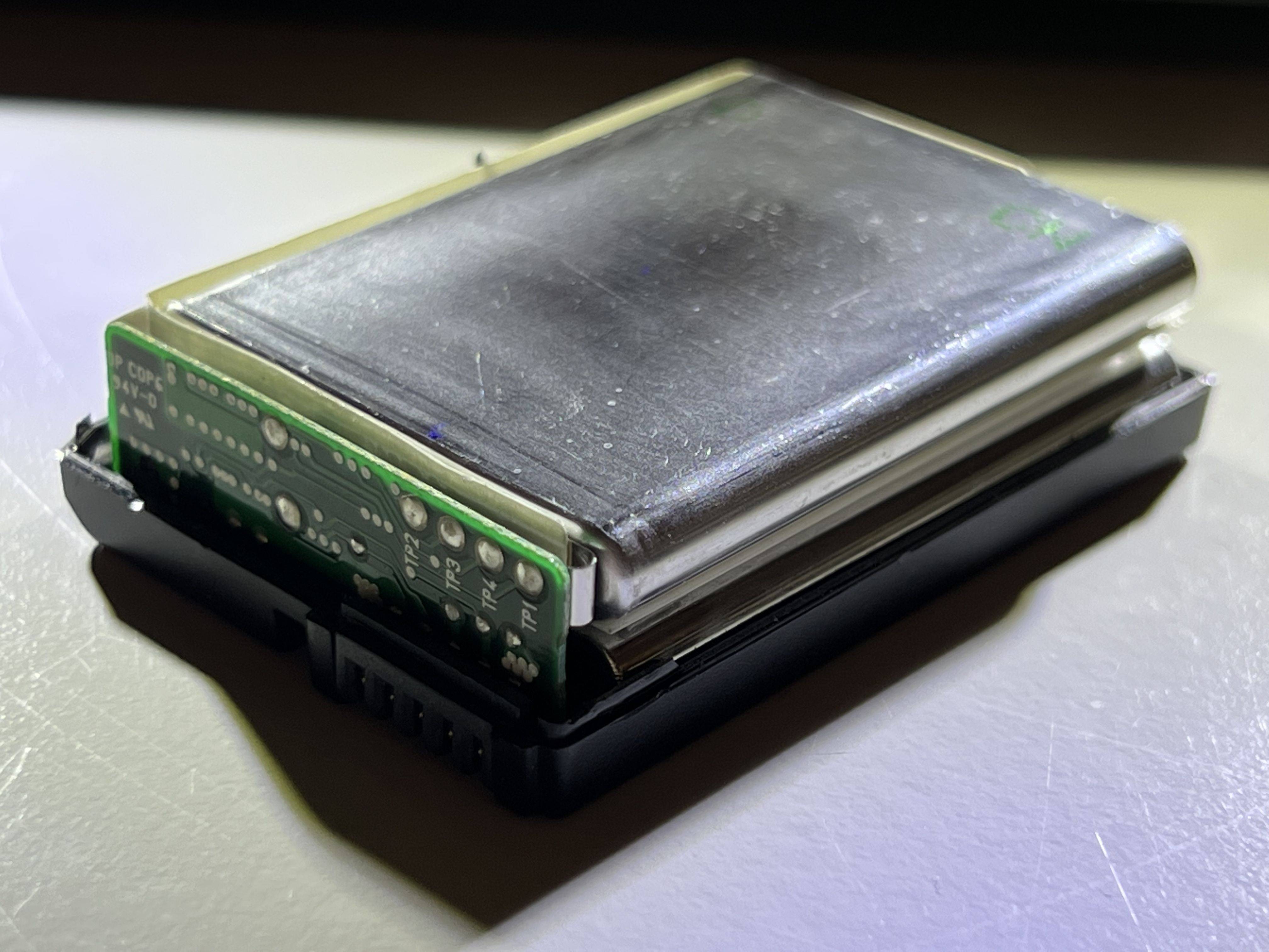
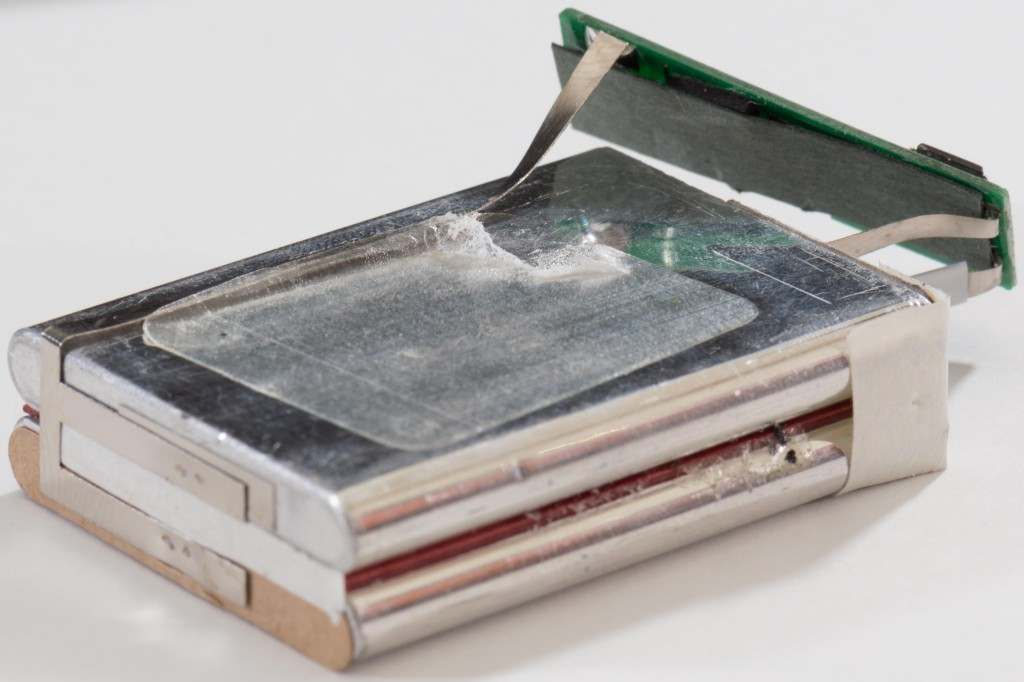
I have a battery that's dead (and a good one). I could try to make one myself - even if it's just for learning purposes. So I took the bad battery apart and took some photo's along the way.
As you can see, there are two separate metal strips running from the PCB to the "bottoms" of the batteries.
There was one other metal strip connected to the top(s?) of the batteries. Unfortunately I'm not sure anymore and didn't take a picture. The batteries have been disposed (properly) and now all I have left is a PCB.
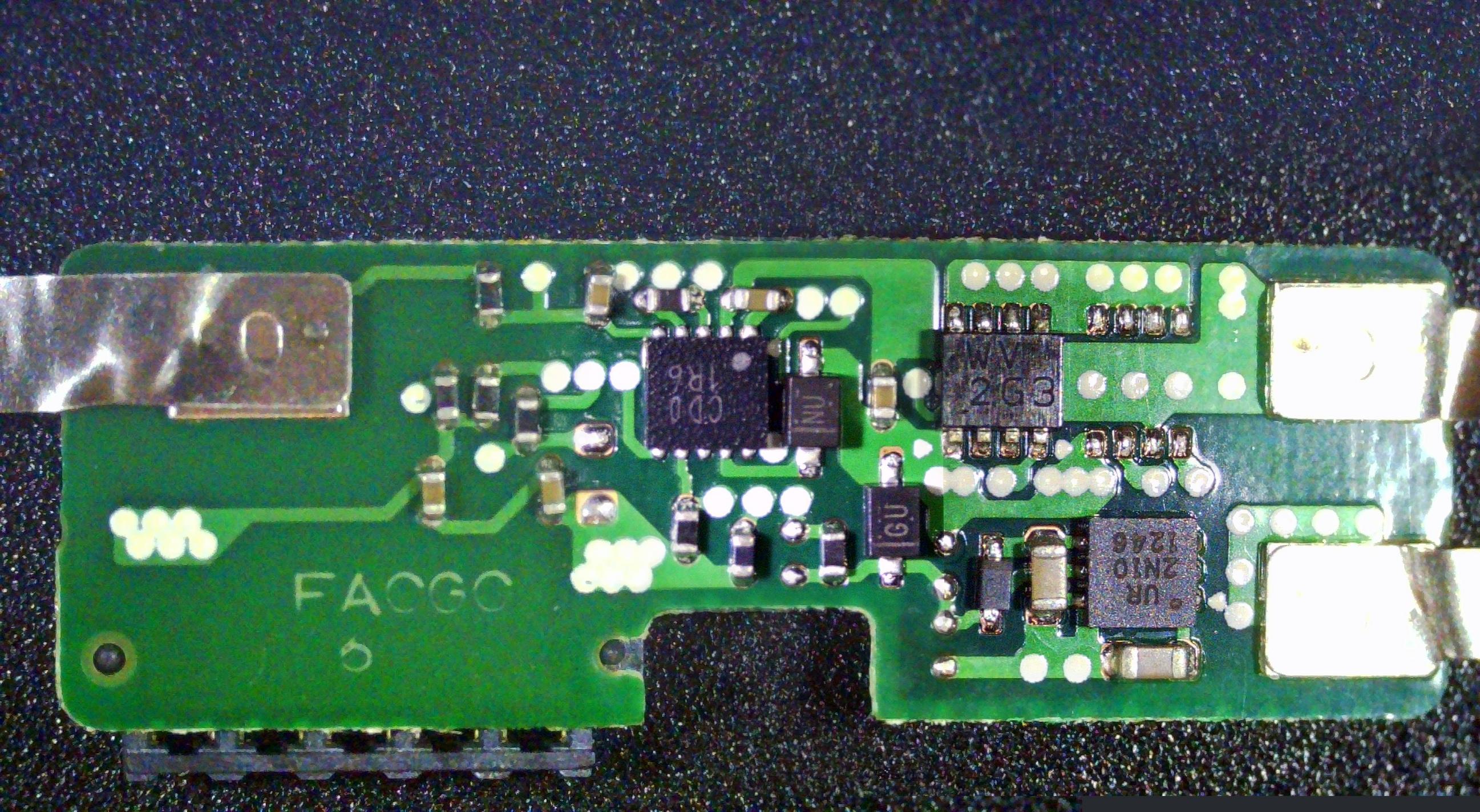
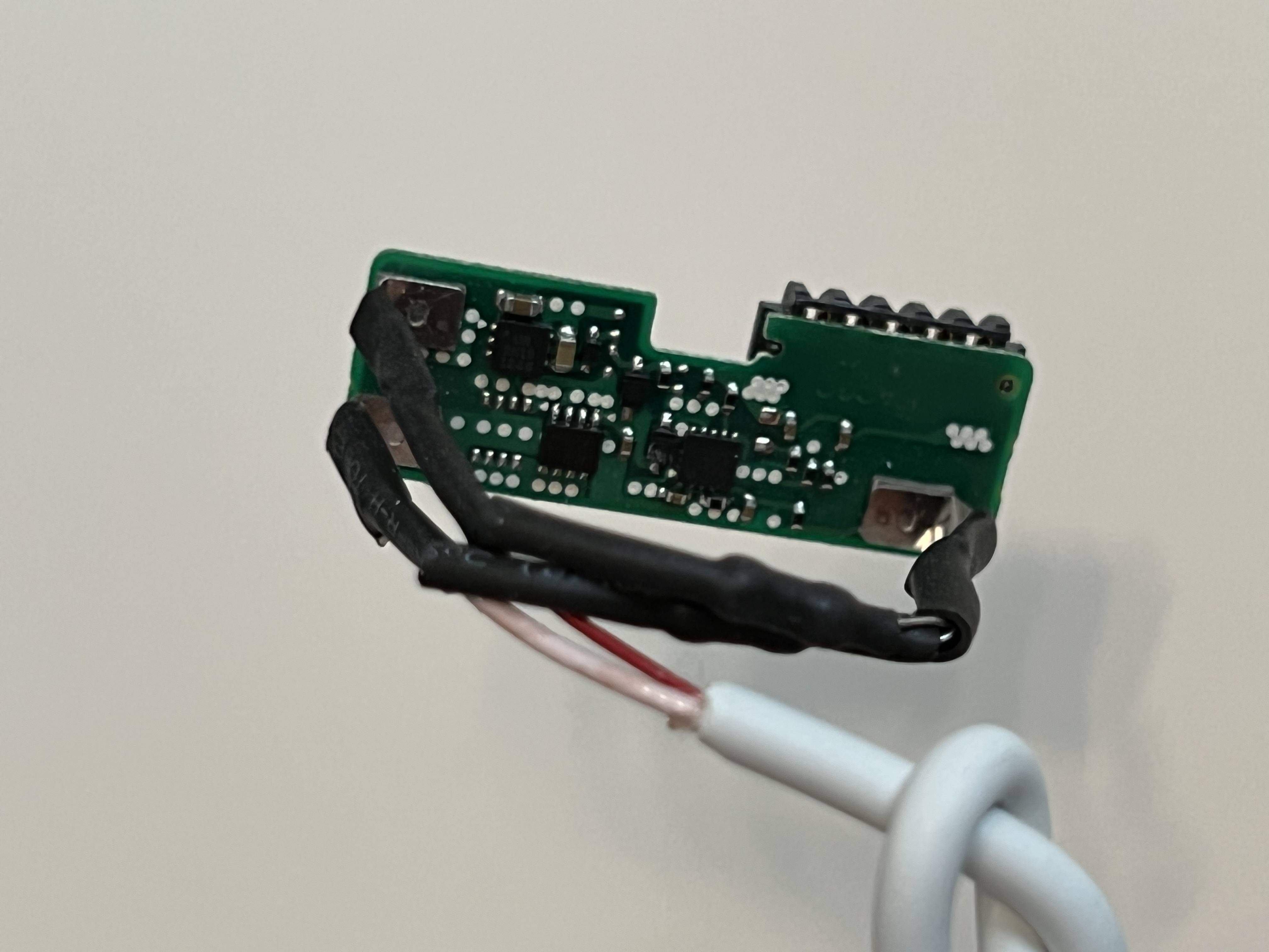
The metal strips and the pads clearly show; one on the left, 2 on the right.
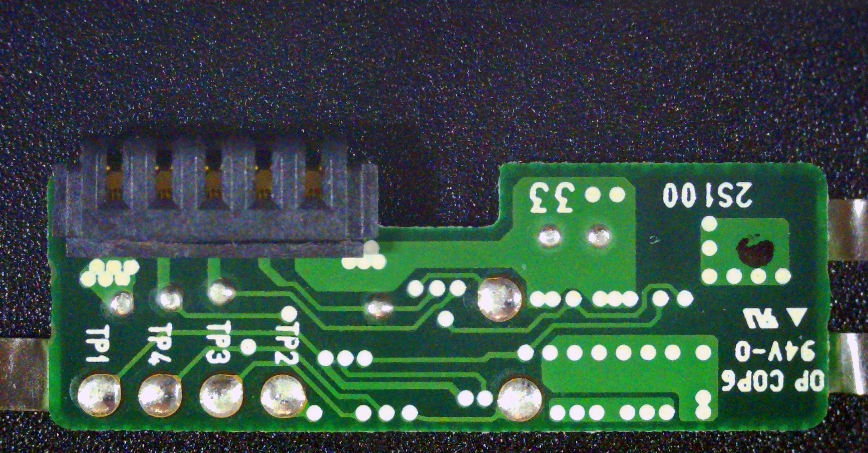
The other side of the PCB. I did find some information on a clone (mine is an original) here. In there is a picture of the clone:
So now I'm thinking (and please confirm or refute) my assumptions:
1) One of the strips should be positive, one should be negative, one should be the center-tap for the BMS to be able to balance the cells. In the above picture of the clone you can see the left strip is connected to the middle of the two cells which I assume are in series (2x 3.7V), so the other two leads should be positive/negative?
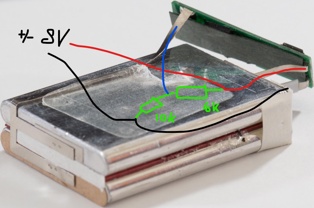
Next, I'm planning to use my bench power supply to test if this is going to work, "faking" cells...
In the below drawing I have assumed a polarity, it may be the other way around but:
I'm assuming the BMS wants to measure about half the voltage at the center-tap - the cells are 3.7V nominal, 4.2V charge voltage. I'm planning to place a voltage divider in parallel and connect it's middle to the center-tap to make the BMS happy.
2) Will this work? And what would be the best values for the resistors? I've chosen quite high values (10K) but that's only because I think it would limit the current to tiny amounts which, in turn, should prevent the resistors warming up etc. but maybe I'm way off or shouldn't be using a voltage divider in the first place?
Ofcourse the cells are gone now - and note that this is the clone, not my battery. Then: all that's left is determining the polarity and which strip is what so I can hook up my cable to my (temporary) bench power supply (to be replaced with a wall wart of some kind, though it needs to be able to deliver up to 4.5A I've read 😱). So:
I'm assuming (see image 3) the left pad/strip will be center tap and the pads/strips on the right are Vin and GND.
3) The thought has crossed my mind that, maybe, when I cut the cells off (one strip at a time) the PCB lost power and, because of "DRM" reasons or whatever, will not (re)activate without me doing some trick of some kind or maybe that may have even bricked it. Maybe someone has some more info on this?
Sorry for the long post and many questions. Any help is very much appreciated!
(Oh, and I'd rather not open the good one)
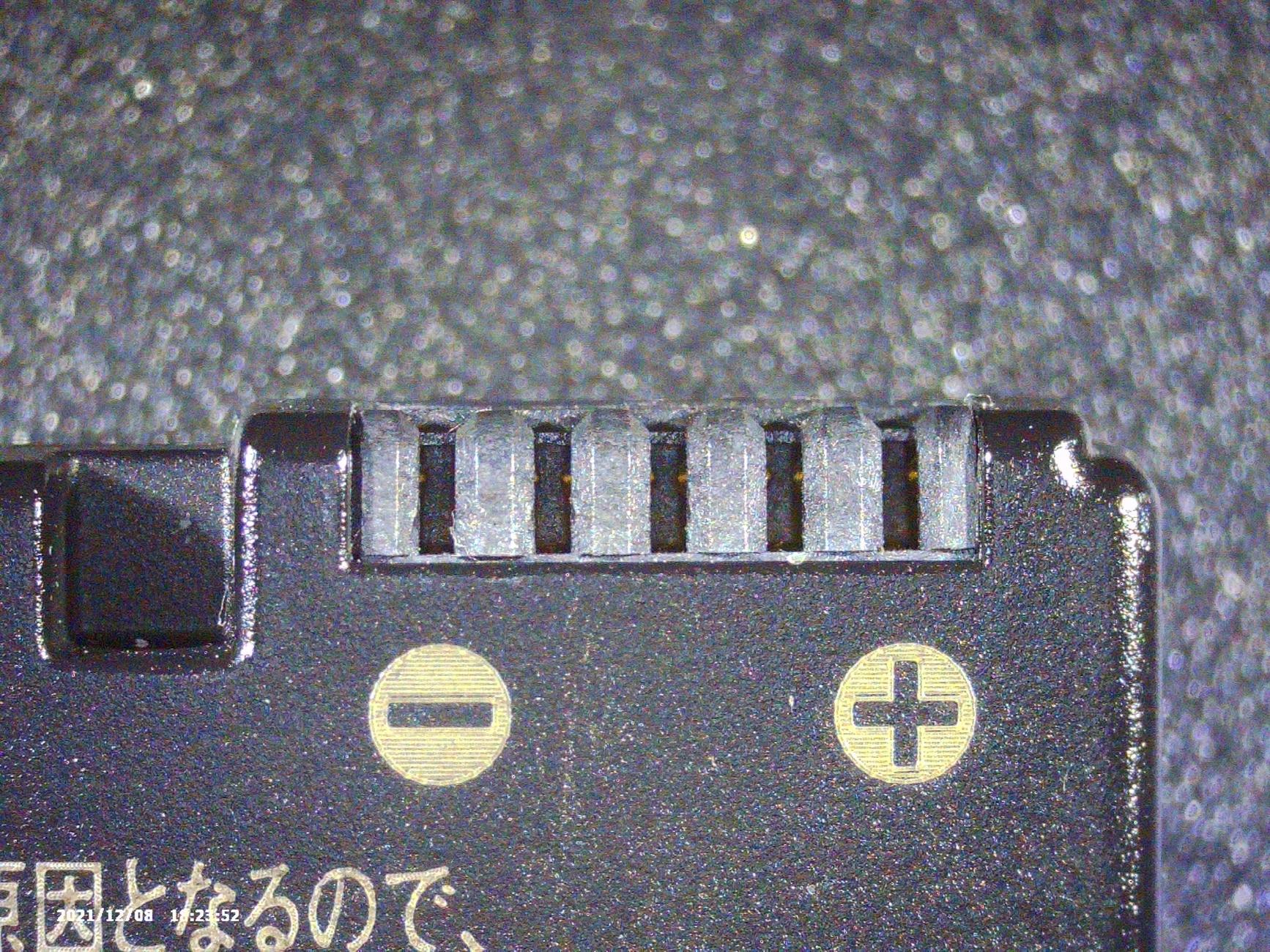
Edit: I just realized some polarity information is on the plastic housing:
Then I can say with certainty that the leftmost pin of the 5-pin connector in image 4 is positive and pin 5 is negative (image 4 is looking at it from the other side, so 'rotated').
Update
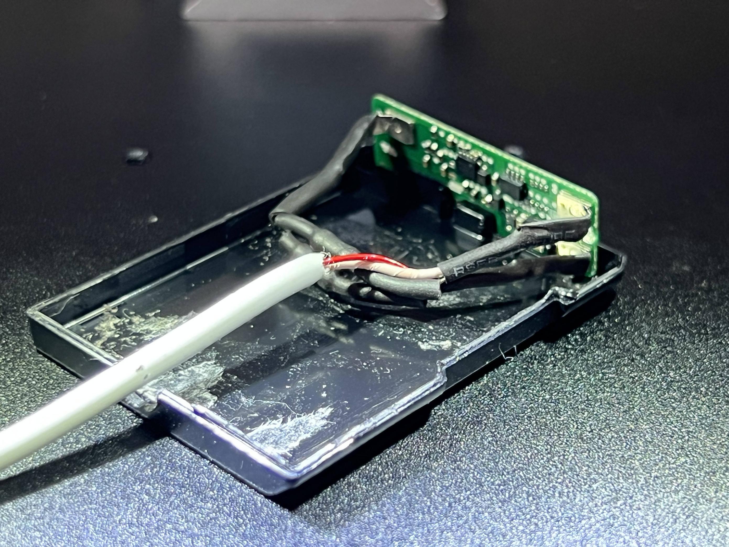
I went ahead and tried it. I connected it up as follows:
Red (positive) goes to the top left pad. White, negative, to the left bottom pad. From both the pads a 10K resistor is connected to the right pad (they are in the shrinktube). Care was taken, using shrinktube, that nothing could short out; the tiny part that isn't covered in shrinktube is where the resistors join to the right pad.
I then put everything back in the casing and tied a (loose) knot in the cable just behind the opening in the casing for strain relief.
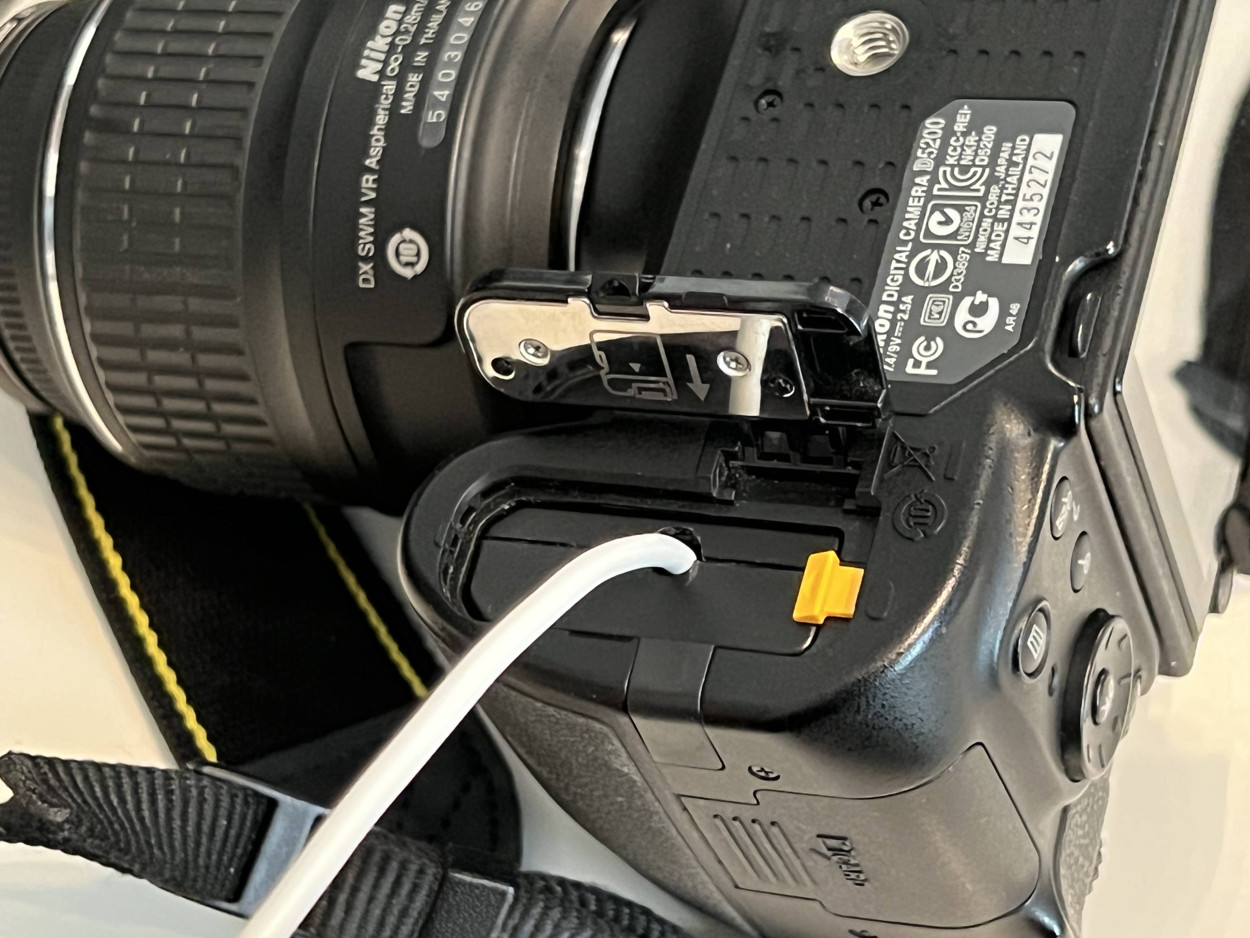
Then I put the 'dummy battery' in the camera. Fingers crossed I don't blow up an expensive device 🤞
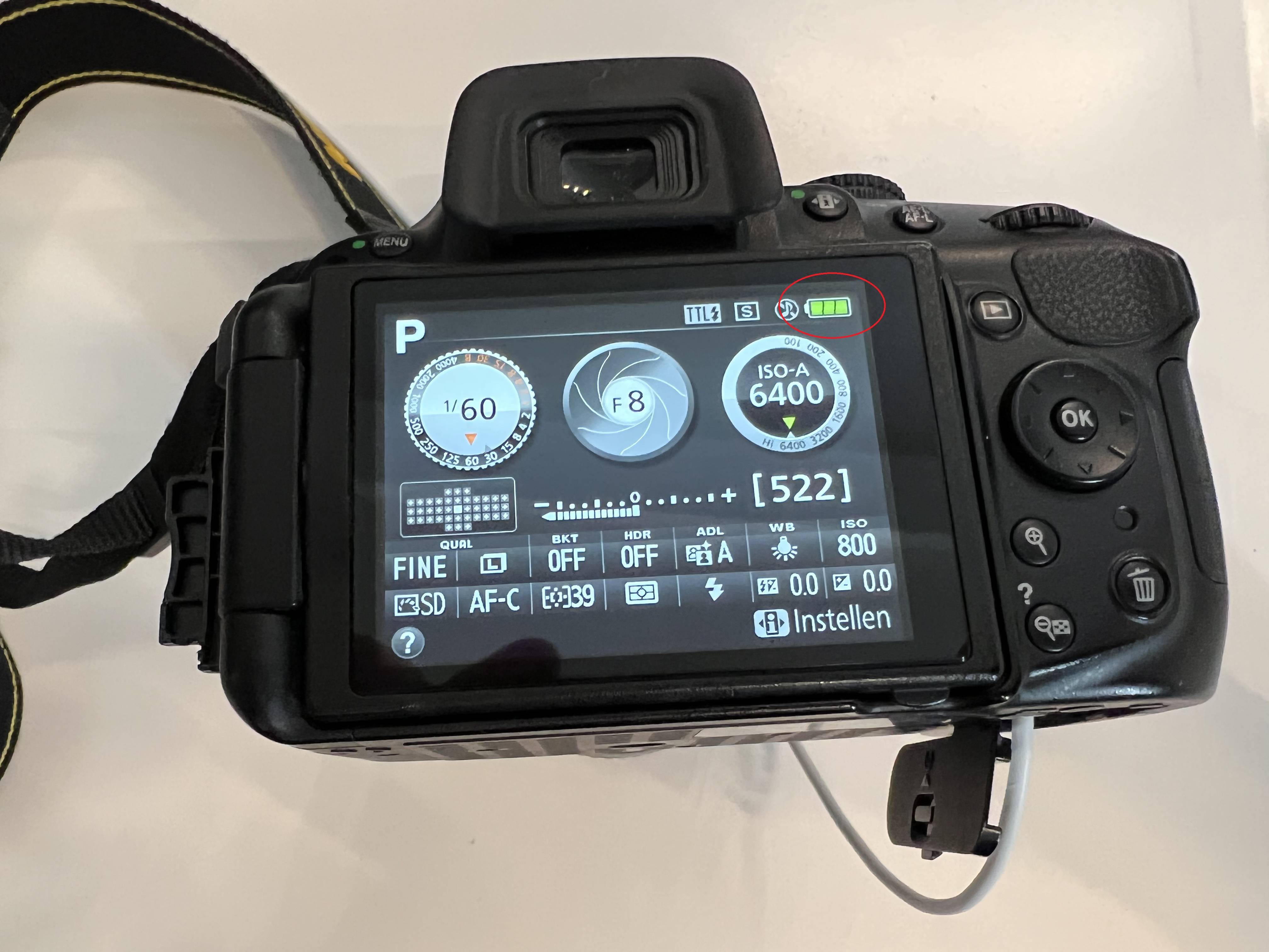
IT VURKS!
The good news is: it works. Or... worked I should say. I powered the camera for some minutes using my dummy battery and everything seemed fine. All was well. So I decided to glue the casing and put a connector on the other end of the cable so I could easily connect it to an adapter ("wall wart") or something. So I soldered a female DC connector, shrinktubed the wires and put the crocodile clips from my bench power supply on another, male, connector and connected the DC jacks. Put the battery back in the camera and switched on the power...
I immediately noticed the voltage to drop to around 5V and the amperage shooting up to the (limited to) 4A I had set my bench power supply to (because this page suggests 9V/4.5A). The camera didn't come on, nothing happened. So I switched off the power after a few seconds. Putting back the good battery in the camera comes back on just fine - pfew!. But the battery board appears to be dead.
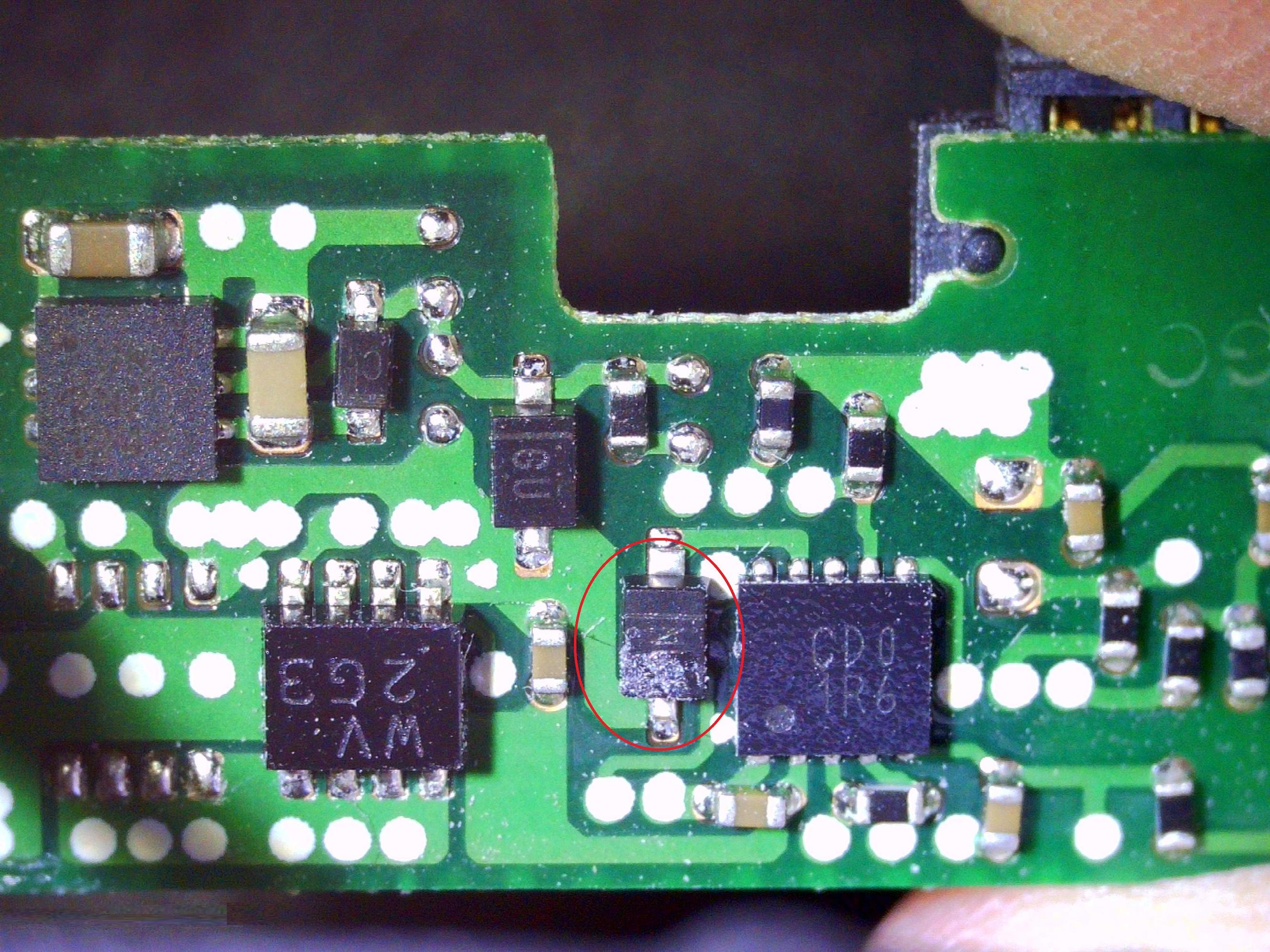
Inspecting the board under the microscope reveals this:
See image 3; before it looked ... better. I have no idea what happened in between; the cable is tested and doesn't short out. The resistors still measure 10K. The DC jacks were suspicious but seem to be OK (not shorted out) as well.
The component appears to be a diode? It's just incredibly tiny; I'm not sure if I'll be able to replace it, and even if I can, I only have through-hole diodes in stock; I'd have to order the SMD one and even then it'll be a gamble if it'll work. I think I'm out of options and will give up on this. I was gonna order a cheap one from AliExpress anyway and, assuming that one works, that will save me from a lot of frustration trying to replace an atom-sized component. Suggestions are welcome anyways - and maybe someone has an idea what went wrong?

