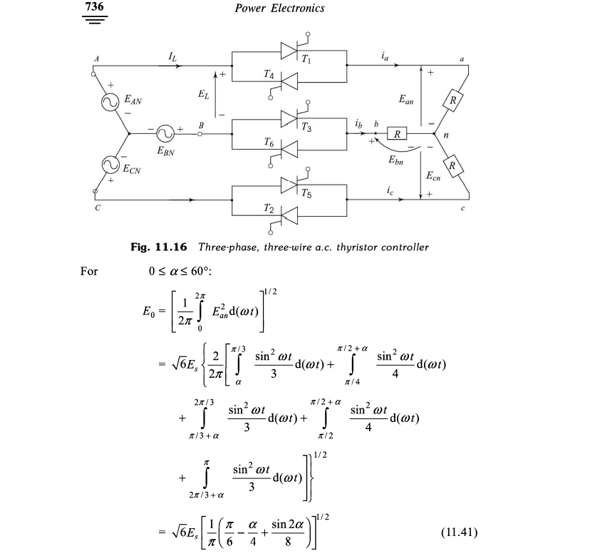
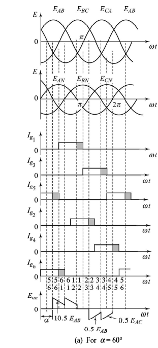
Can someone explain how do we end up with those integration intervals in three-phase AC regulators?
-
\$\begingroup\$ Neutrals not connected ? \$\endgroup\$– Antonio51Commented Mar 12, 2022 at 19:07
-
\$\begingroup\$ Is there a problem with drivers? IG6 start after IG5, IG2 & IG1 ?, IG3 & IG4 ? \$\endgroup\$– Antonio51Commented Mar 12, 2022 at 20:37
-
\$\begingroup\$ @Antonio51 yes, they're not connected. I've checked multiple resources, including three books and they all have the same circuit and explanation, a bunch of integrals without additional information. \$\endgroup\$– Dardan LubishtaniCommented Mar 12, 2022 at 20:37
-
\$\begingroup\$ Anyway, there is a problem in "driving" ... If "neutrals" are connected, then the circuit can be seen as 3 1-phase regulators. It is what I guessed in my answer if it can help. \$\endgroup\$– Antonio51Commented Mar 13, 2022 at 9:00
-
\$\begingroup\$ I will try "simulate" your configuration, but with a "driving" corrected. \$\endgroup\$– Antonio51Commented Mar 13, 2022 at 9:04
2 Answers
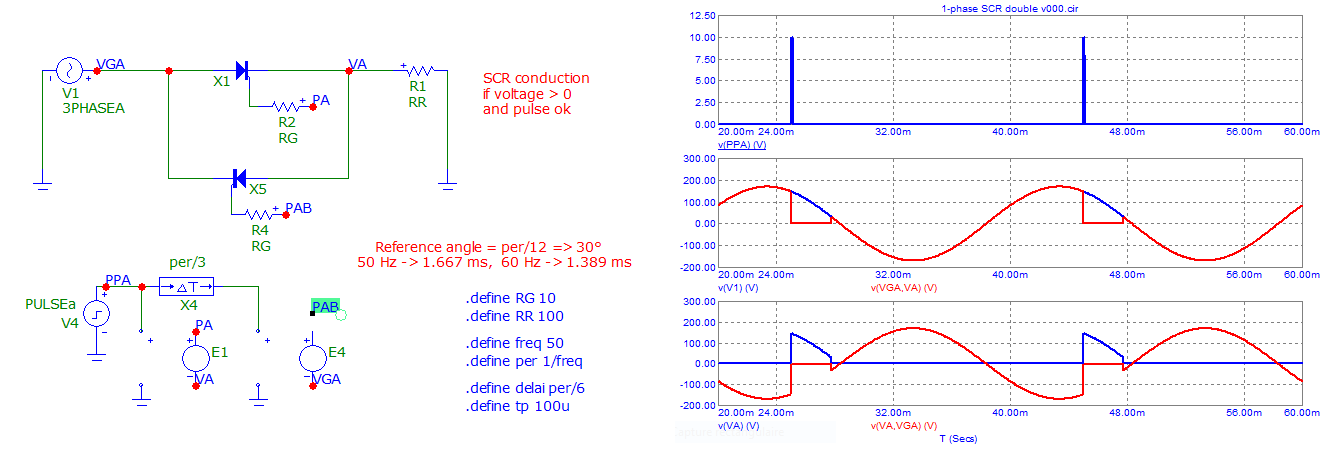
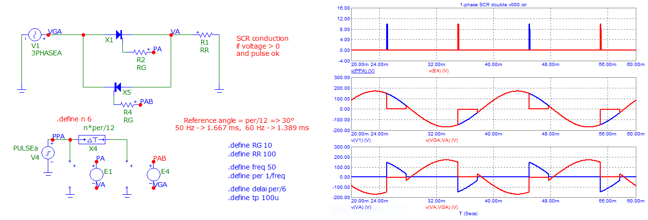
Here is what one gets when one SCR is fired.
The other can only be fired if the voltage of its Vak is positive only ...
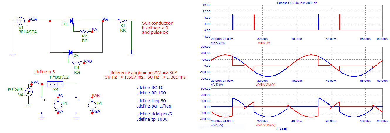
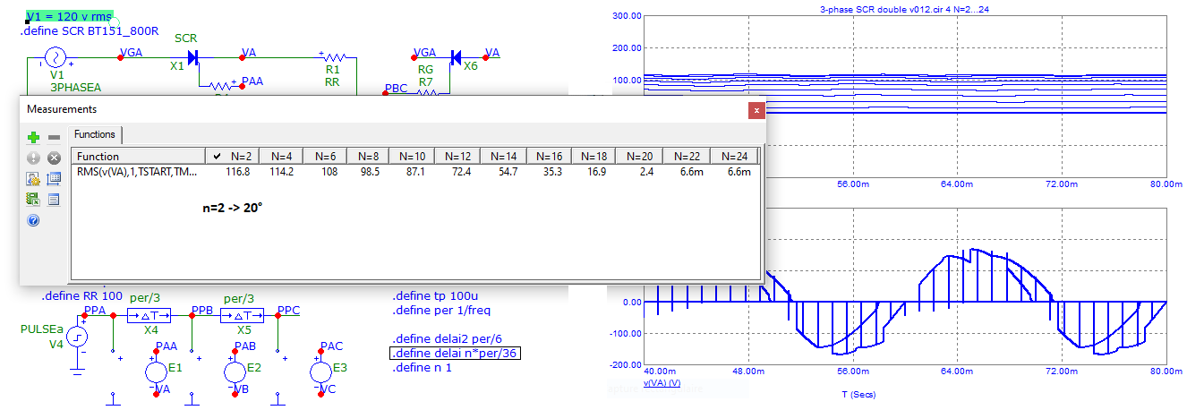
Here when SCR bis fired at n=3, see the Load resistor voltage (VA).
And when n=6
-
\$\begingroup\$ now that I think of it we don't need those neutrals for this circuit. Supposing T1 and T6 are conducting, we get a 0.5EAB voltage drop across the load R. If we follow the sequence shown at the bottom we will get that waveform. The thing I'm not understanding is those integral boundaries, how do we end up with those? \$\endgroup\$ Commented Mar 13, 2022 at 9:38
-
\$\begingroup\$ Ok. One "neutral is needed for the simulator. And the "driving" of SCR is not the same. When you will fire one SCR, just see if the voltage across it is "positive". Remember that the SCR already fired will conduct until the voltage across it became "negative". This will give the limits of integration of the concerned wave. \$\endgroup\$ Commented Mar 13, 2022 at 9:50
-
\$\begingroup\$ Another point. As we have 6 points "drive", and 6 points natural "stop", we have twelve "sections" of waveform on one load R. NB: With 2 sequences "drive", the strategy of "firing" seems to be a bit complicated. \$\endgroup\$ Commented Mar 13, 2022 at 9:55
-
\$\begingroup\$ I think I'm getting the idea based on your previous comment mentioning for how long the SCR will conduct. Thank you very much! \$\endgroup\$ Commented Mar 13, 2022 at 10:26
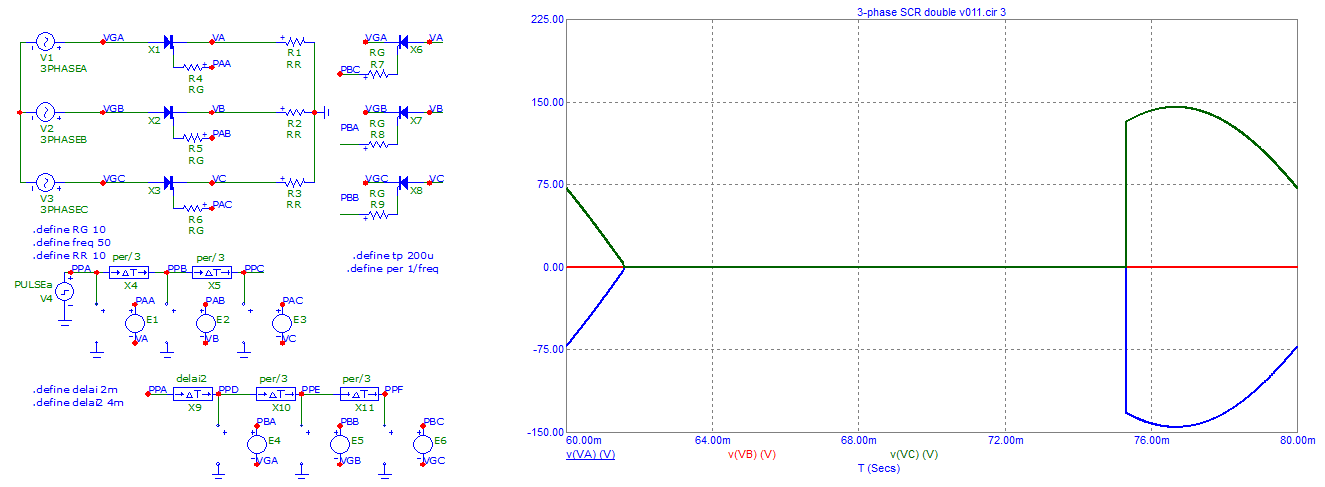
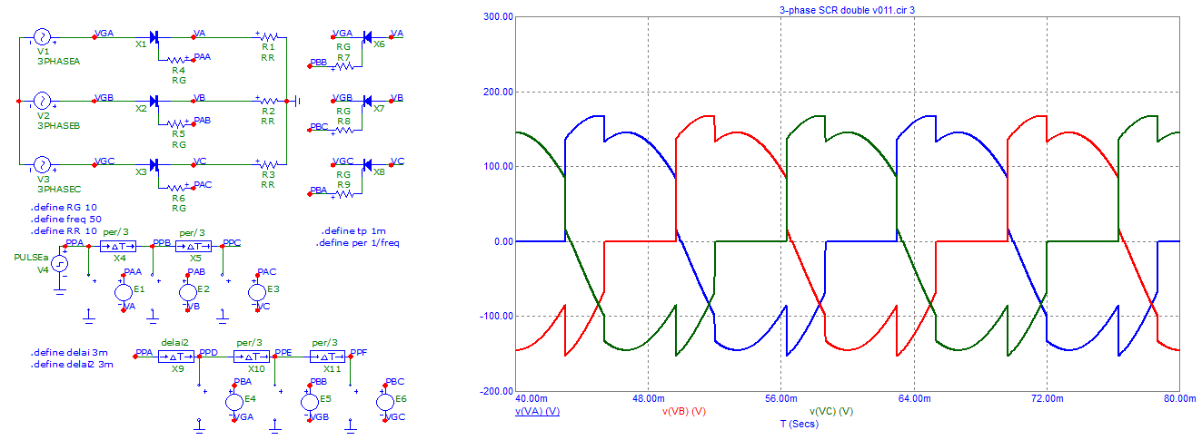
Here what one get when it is a 3-phase circuit.
Ean ... does not seem to be what is in the book ...
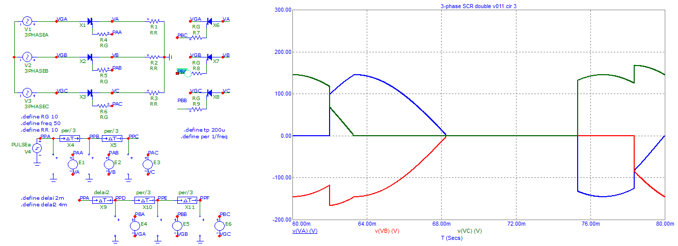
I did 3 simulations.
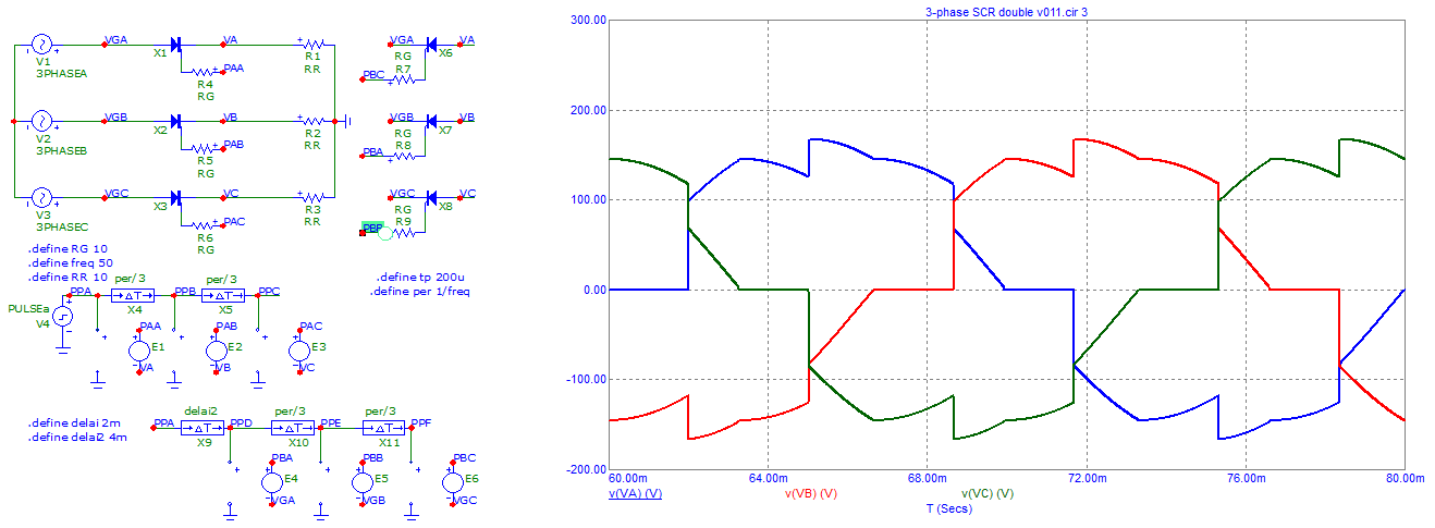
One with only 1 reverse SCR fired, Second with 2 SCR fired, Third with 3 SCR fired.
One can see that waveforms are not the same ... (unless error.s)
And this one for another "drive" sequence.
Here is the calculation of "RMS voltage" versus "phase angle" drive.

