1
\$\begingroup\$

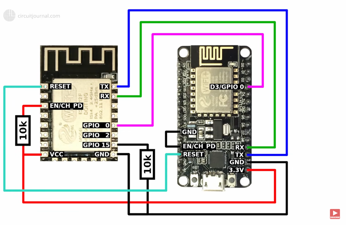
I used this wiring schematic for a couple of my ESP8266-12F projects for programming mode:

enter image description here

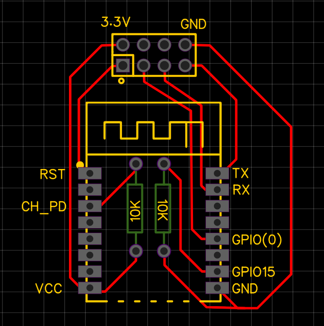
As I built enough confidence with the module, I decided to go ahead with a PCB design. When I try to upload a sketch, it wouldn't go into programming mode although I think my design is correct. I checked the connections between pads and headers and they all connected. Am I missing something here? Would you please check the connections and let me know of possible cause?

esptool.py v3.0
Serial port COM4'
Connecting........_____....._____....._____....._____....._____....._____...._____

esptool.FatalError: Failed to connect to ESP8266: Invalid head of packet (0xE0)

enter image description here

\$\endgroup\$
1
  • \$\begingroup\$ I had a similar problem recently. It was due to not enough capacitance on the power supply. Fatten up your gnd and vcc tracks and add a 22uF 25V ceramic capacitor close to the module pads. Note that it is not a good idea to run tracks under the antenna or even the pcb. \$\endgroup\$
    – Kartman
    Commented May 14, 2022 at 19:12

1 Answer 1

1
\$\begingroup\$

Your top image shows TX to TX and RX to RX. Is that really correct or should it be TX to RX?

\$\endgroup\$
3
  • \$\begingroup\$ I used the upper wiring tens of times. However, I swapped TX & RX but got the same issue. \$\endgroup\$ Commented May 14, 2022 at 11:04
  • \$\begingroup\$ this answer should really be a comment \$\endgroup\$
    – jsotola
    Commented May 14, 2022 at 18:34
  • \$\begingroup\$ Your enable pin is pulled low on one and high on the other. And, are you enabling GPIO-0 to the proper high/low to enable programming of the ESP12F? \$\endgroup\$ Commented May 14, 2022 at 21:17

Your Answer

By clicking “Post Your Answer”, you agree to our terms of service and acknowledge you have read our privacy policy.

Not the answer you're looking for? Browse other questions tagged or ask your own question.