0
\$\begingroup\$

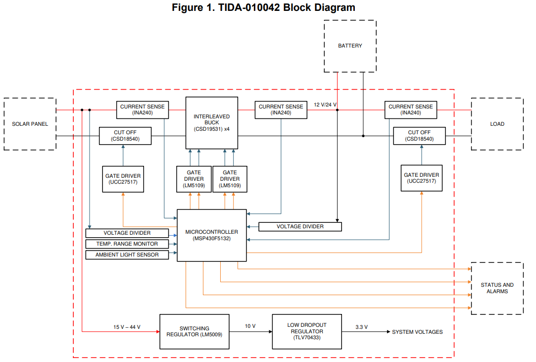
I am currently planning to design an MPPT solar charge controller and I am trying to follow a reference design from TI - TIDA 010042.

I am planning to use arduino as the microcontroller for this project.

I tried to learn and make some research about MPPT and how it works, but I still have some remaining principle not clear.

I will start by the conditions:
I will use 12V battery and my load contains a motor the motor works only if needed otherwise the system has a camera which take some pictures and do analysis (variable load)

I have 2 approaches for this:

  1. use the same block diagram as TI and implement the charging algorithm in the uC
  2. Remove the charging algorithm from the uC and add a dedicated charge IC between the MPPT block and the battery.

I am not sure if the second method can work or not (I am currently in the first phase of the design).

Core question

For the first approach let's take at a given condition the solar panel operate at Vp and Ip the MPPT bloc will try to change the duty cycle of the buck or boost or buck/boost converter to mimic the load which extract the max power (P&O algo) now the panel output Ipmax and Vpmax with that specific duty cycle the DCDC will output a correspondant Idcdc and Vdcdc let's assume that the Idcdc at max condition is 5A and the battery need to be charged at 3A (constant current phase) in that case we need to change the duty cycle to output 3A instead of the most efficient 5A and that let the solar not operate in the MPP region.

Could you please provide me your support to understand better the logic behind it? (I attached the bloc diagram of TI)

enter image description here

\$\endgroup\$
4
  • \$\begingroup\$ Does this answer your question? Solar panel short circuit \$\endgroup\$
    – D.A.S.
    Commented Jul 9, 2022 at 12:39
  • \$\begingroup\$ To get matched max power , conjugate impedances must be matched by sensing V,I in each stage. \$\endgroup\$
    – D.A.S.
    Commented Jul 9, 2022 at 12:42
  • 1
    \$\begingroup\$ I think you answered your own core question: if you can't put the maximum power anywhere, operating at maximum power makes no sense. \$\endgroup\$ Commented Jul 9, 2022 at 12:45
  • \$\begingroup\$ so you need to prioritize the charging current of the battery and the voltage level over the MPPT algo? \$\endgroup\$
    – fedi makni
    Commented Jul 9, 2022 at 12:52

1 Answer 1

1
\$\begingroup\$

Arduino¹ really isn't the right microcontroller platform for this kind of system. What you need is something that makes it easy to control the PWM units with a guaranteed maximum latency, you need a strict watchdog timer and a interrupt-driven supervision of things like overcurrent. Arduino is a slow, busy-loop driven operating system that makes all these things impossible, or at least impossible if you don't work around the arduino software platform itself. But it's easy to write software for, if you needed none of these things!

You need to realize that the MSP430 in the TI block diagram is the separate, dedicated controller IC that you think you want to use for your second approach – you need no less than something that you can program to control the buck stages, supervise currents and voltages and the charge state. That's clearly a job for a microcontroller! Just not for one running Arduino. Adding an Arduino system to your microcontroller here feels like it adds nothing the actual charge controlling microcontroller, but fragility and complexity!

So, yes. You should stick to the TI block diagram, and no, you should not use Arduino. There's good real-time operating systems out there that allow you to do this, safely, on appropriate hardware, for free. A good real-time OS doesn't take any time away from your actual main job, it just makes it easy to set up things and do regular maintenance/checking jobs without having to worry about data consistency / race conditions / missing interrupts.

The classic choice here would probably be FreeRTOS, which I find somewhat usable, but hard to port to new hardware. You would probably, however, use an eval board anyway, for which there should be a FreeRTOS port.

Personally, I prefer ChibiOS for such small control systems as you need to build, but that means you might need to port it first, which is probably prohibitively complex.

The trend for easy-to-program RTOS seems to be going towards Zephyr, though I have zero experience with it personally. I guess, however, that something like an ST Nucleo F334R8 would allow you to use any of these operating systems, at your preference, and have more than enough compute power to make it easy to build such a system in short time, whilst even having a connector that is compatible with arduino uno v3. And it's relatively cheap and available world-wide. Has all the necessary PWM units, watchdogs, comes with a debugger/programmer for free, enough timers / PWM units for your gate drivers, enough ADCs for voltage sensing, three comparators for overcurrent sensing, 5V-tolerant IOs; basically, more than any Arduino board would offer.

Note that I don't consider writing code for Arduino any easier than for one of the big RTOSes. Yes, you do need to know how to write code, but when writing a charge controller, not knowing your programming well enough will lead to expensive mistakes where you short power transistors, overcharge or deep-discharge expensive batteries or overvoltage devices, so, no matter whether you're doing Arduino or any other operating system, you will always want to test your software properly. Arduino's libraries actively make that harder than necessary – you can't compile most for your a "pseudo" microcontroller that's actually just software running on a PC.


¹ "Arduino" is not actually a single type of microcontroller - there's actually very many different microcontrollers called "Arduino", it's the software that runs on it.

\$\endgroup\$
4
  • \$\begingroup\$ Hello, Thank you very much for your comment. I understand that i need to change the arduino uC, i can use esp32 for example but actually that's not the answer i am looking for. I would like to have an idea about the logic behind the charging while keeping operating at the MPP region. if in the MPP the solar panel output a very high current compared to the required charging current limit of the battery, that can lead to serious problem or even lower the efficiency of the system \$\endgroup\$
    – fedi makni
    Commented Jul 9, 2022 at 12:18
  • \$\begingroup\$ you can use any microcontroller you like, as long as it has 1. watchdogs, 2. enough hardware PWMs, 3. low-latency interrupts, and, 4. the software you run on it can make use of that. I don't think the ESP32 does that. \$\endgroup\$ Commented Jul 9, 2022 at 12:44
  • \$\begingroup\$ Thank you for your comment. Do you have any answer regarding the actual question? \$\endgroup\$
    – fedi makni
    Commented Jul 9, 2022 at 12:49
  • \$\begingroup\$ I already commented directly under your question! \$\endgroup\$ Commented Jul 9, 2022 at 13:48

Your Answer

By clicking “Post Your Answer”, you agree to our terms of service and acknowledge you have read our privacy policy.

Not the answer you're looking for? Browse other questions tagged or ask your own question.