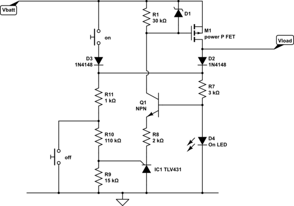
M1/IC1 form the latching 'thyristor type' power switch. It draws no power when off, and little when on.
The TLV431 (not the right symbol, this was close) is designed as a 3 terminal shunt regulator, that maintains the sense voltage at 1.24v. You could think of it as a high gain NPN transistor, with a very precise 1.24v base voltage. Q1 is used as a cascode current source to get the signal up to the high voltage present at the FET, as the TLV431 is only suitable for 6 or 16 V, depending on manufacturer.

simulate this circuit – Schematic created using CircuitLab
In order to inhibit switch-on if the battery is low, the ON switch connects Vbatt to the voltage sense divider chain via D3, and conveniently the ON LED to show that something is happening. If Vbatt is high enough, IC1 turns on, and sends a current through Q1 to turn on M1, connecting the load, and maintaining the sense voltage via D2. The ON button can now be released. D1 limits the gate voltage for high voltage battery inputs. D2 prevents the ON switch from powering the load directly.
I'm using a blue or white ON LED for double duty as a regulator, the slope resistance is an order of magnitude better than a Zener at this voltage. Choose R7 for a few mA if it's needed as an ON indicator, or for 100 uA if it's not.
When coming to turn the circuit off manually, large capacitors in the load may hold the load voltage above the battery minimum threshold for long enough to be tedious, pressing the off button and waiting for it to stop. R11 allows you to actively load the output when turning off, choose a smaller value of R11 to discharge faster. The maximum current you can draw from the load is limited by R11 pulse load handling, D2 and the off switch current handling. Don't omit R11, unless you also omit the off switch, as it protects the off switch from a high current from the load's charged capacitors.
Use of D2 and D3 reduces the threshold accuracy slightly, but not significantly. R9 and R10 values are shown for approximately 11 V threshold, about the minimum for nominally 12 V lead acid batteries (this was originally a design for a 12 V switch, but with suitable ratings/values for Q1, M1, R7 and R10 can work for any high voltage). Increase R10 appropriately to drop out at your battery minimum voltage, allowing for the D2/3 and R11 voltage drops.

