1
\$\begingroup\$

enter image description here

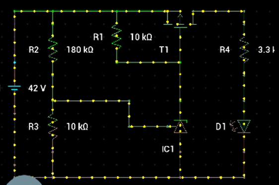
My purpose is to make cutoff circuit that will cut battery voltage before 40 V else after 40 V it will be in working.

Above circuit I tried and it’s working fine but I'm confused because as per the datasheet TL431 cathode volt is 36 VDC max.

Just let me know if anyone can help me to make sure this circuit is theoretically correct because during my test TL431 cathode was getting 38 V on 39 V input. 1 V drop at R1 (10k) resistor that is exceeding the limit.

\$\endgroup\$
4
  • 1
    \$\begingroup\$ 40V will damage the TL431. See here how you can reduce the TL431 voltage. electronics.stackexchange.com/questions/606428/… or here electronics.stackexchange.com/questions/627144/… \$\endgroup\$
    – G36
    Commented Sep 15, 2023 at 14:02
  • 1
    \$\begingroup\$ Consider an N-FET to pull down the gate of the P-FET and a Zener clamp to limit Vgs of your P-FET. \$\endgroup\$
    – winny
    Commented Sep 15, 2023 at 16:21
  • 1
    \$\begingroup\$ The TL431 is the wrong IC because it has a linear output. You want two states: on or off. Therefore, you need an IC with a digital output. Such ICs include comparators and power supply supervisors. \$\endgroup\$ Commented Sep 15, 2023 at 17:47
  • 1
    \$\begingroup\$ If that is a Li-ion battery and your goal is protect it, a low voltage cutout won't do so. What you need is a BMS that cuts of the power if a single cell is low.Your circuit cuts off if the total battery voltage is low, by which time it's too late to prevent damage to a cell. \$\endgroup\$ Commented Sep 15, 2023 at 17:48

0

Your Answer

By clicking “Post Your Answer”, you agree to our terms of service and acknowledge you have read our privacy policy.

Browse other questions tagged or ask your own question.