4
\$\begingroup\$

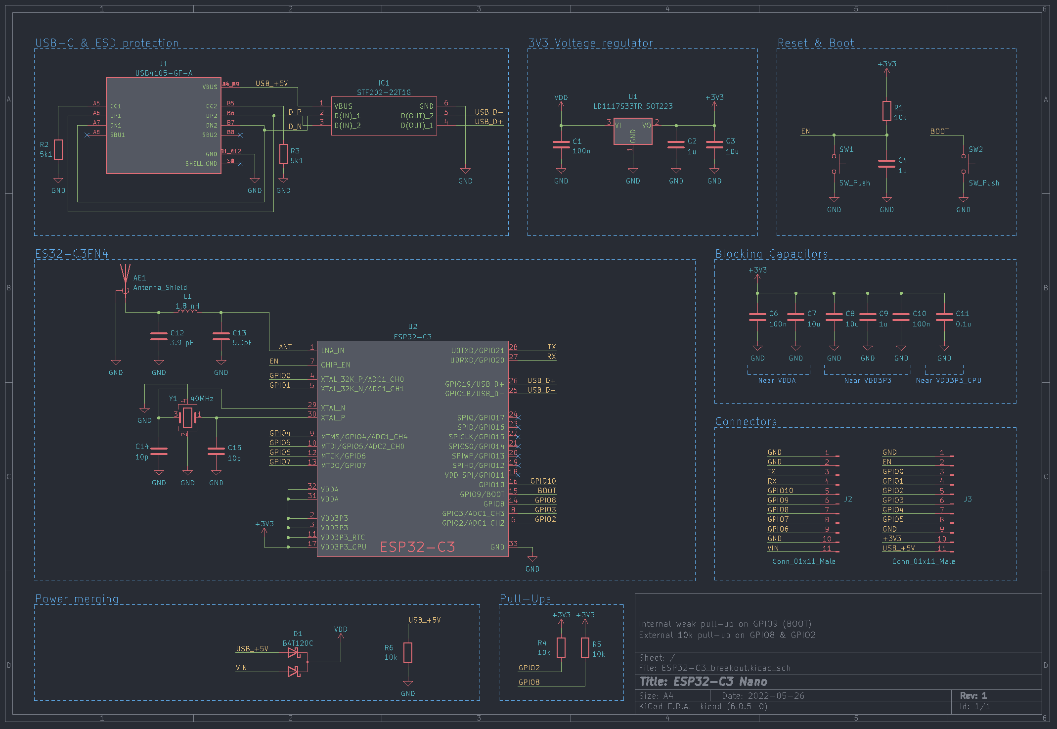
My setup: I have an ESP32 IC (and some circuitry around it) which is powered by USB-C or external power. These two power inputs are "mixed" together using 2 Schottky diodes. (GitHUB repo for context, but not important).

The problem: This setup works really great, until I try to power it externally and have the USB-C cable connected also. Remember, due to the power rail mixing, this should be fine, but the computer does not want to recognise the device now.

Solution? I found out that just by connecting a 10 kΩ pull-down resistor to the USB-C line solved the issue and I was able to power it externally and program it via USB-C.

Question: So does the USB-C controller inside my MacBook M1 require some power draw from the device in order to recognise it? I never heard of this issue before and I'm kind of confused.

Edit: Posted schematics here: enter image description here The pull-down resistor in the "power merging" window is just my hot fix.
\$\endgroup\$
7
  • 1
    \$\begingroup\$ The only issue I can think of is that some power banks turn off after some timeout if the current drawn is too low. Apart from that, you should be allowed to draw as low current as you want. \$\endgroup\$
    – winny
    Commented Aug 25, 2022 at 6:46
  • \$\begingroup\$ You may have other design errors which can't be verified without schematics. And there are no schematics anywhere, even if the project files are. Post the schematics. \$\endgroup\$
    – Justme
    Commented Aug 25, 2022 at 8:49
  • \$\begingroup\$ @Justme Schematics added to GitHUB and here as well. \$\endgroup\$
    – Kralik
    Commented Aug 25, 2022 at 12:54
  • \$\begingroup\$ @winny Hmm, that could be a possible bottleneck too, but if you need to power it through USB-C, then the whole board will power of it and it appears to be fine. I could not find a use case where you will just power it through USB and externally \$\endgroup\$
    – Kralik
    Commented Aug 25, 2022 at 12:56
  • \$\begingroup\$ So which scenario does not work? Plug in computer first, then external supply? Or external supply first, then computer? \$\endgroup\$
    – Justme
    Commented Aug 25, 2022 at 14:07

1 Answer 1

1
\$\begingroup\$

It is more likely that there is a leakage via D1 from VDD to VBUS which, without any load, creates some measurable voltage level on VBUS. Presence of VBUS voltage before CC connect is a violation of Type-C specs, and likely the PD controller in M1 blocks this connection as potentially dangerous. With the 10k load this voltage is likely below allowable threshold, and the M1 connects.

\$\endgroup\$
1
  • \$\begingroup\$ This seems like the most plausible thing, thanks! \$\endgroup\$
    – Kralik
    Commented Sep 6, 2022 at 5:26

Your Answer

By clicking “Post Your Answer”, you agree to our terms of service and acknowledge you have read our privacy policy.

Not the answer you're looking for? Browse other questions tagged or ask your own question.