22
\$\begingroup\$

I am a math student with some background in physics so apologies if the question is naive - but I'm trying to understand how large electrical grids like the Eastern Interconnection maintain locally a consistent phase, when it seems like the grid contains loops, i.e. two interconnections between two points, which are of different lengths. The distance to travel a half phase on the American power grid is 1550 miles, and there seem to be loops in the American grid whose size is a significant fraction of this. Doesn't this mean that significant amounts of power would be lost due to misalignment along these kinds of loops?

Or am I misunderstanding what happens here?

\$\endgroup\$
11
  • \$\begingroup\$ "How do large electrical grids stay in phase?" The phase in the grid is not the same at all the nodes in the whole grid ... because it is the phase that regulates the need for power at one node. \$\endgroup\$
    – Antonio51
    Commented Sep 4, 2022 at 8:49
  • 1
    \$\begingroup\$ Hum ... >there seem to be loops in the American grid whose size is a significant fraction of this.< So, are you sure that there are "loops"? Where? What devices are involved along the loops? \$\endgroup\$
    – Antonio51
    Commented Sep 4, 2022 at 20:32
  • 2
    \$\begingroup\$ @Bergi it is not about the copper. It is about the dielectric material in which the E-field travels. For the most part, in a power transmission line, it seems like the dielectric is just air. But maybe the towers or the proximity to planet earth could have some effect. \$\endgroup\$
    – user57037
    Commented Sep 4, 2022 at 23:04
  • 1
    \$\begingroup\$ @Ferrybig we are not all talking about the same thing. This isn't the same as RF transmission line theory. I was not considering the impedance effect on the source. I am just noting that 1550 miles is long enough to have some phase shift even at 60 Hz. \$\endgroup\$
    – user57037
    Commented Sep 5, 2022 at 7:32
  • 1
    \$\begingroup\$ Two interconnections between points of different lengths - that's because you're choosing the wrong points. If you move one point along the loop, you will find that every loop actually consists of interconnections of the same length \$\endgroup\$ Commented Sep 5, 2022 at 15:24

4 Answers 4

9
\$\begingroup\$

It is a "complicated" question. (see this). This?
Should search "how" "power flow" is made into the grid through "distributors" of energy.

This can't receive an answer if you don't know all the characteristics of the "whole" network, although it can be locally modified when one adds a new node (but then, in phase with the injection point, as is done when adding a "local" PV network).

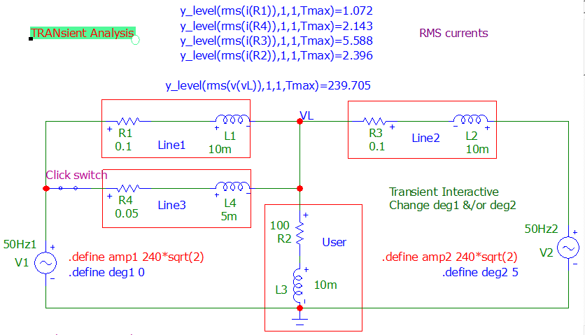
Here is a "simple" example "showing" that it is the "phase" of the voltage generators that are modified to make "circulating" powers in the network (ok, local losses line can change a bit, because "currents" are modified). Lines are also simplified to an equivalent "R-L" circuit.
The power into the Load remains "constant".

Line3 is a new line added to the network (shorter than the others).
What you see is that the cross point (0 degrees, red circle) is shifted to the left (-0.7 degrees, blue circle), because V1 has now more influence than V2.
So, V1 "inject" more power into the Load than V2 (0 degrees, blue rectangles).
This behavior can be changed by "shifting" the phase of V1 as you can see.
NB: this can be done although the amplitude of generators remains the same.

enter image description here

Interactive file made with microcap v12.

enter image description here

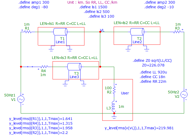
Interactive file with "High Voltage lines", parameter code "BlueBonnet".
Made with microcap v12. Parameters line : R, L and C, a bit more difficult.

enter image description here

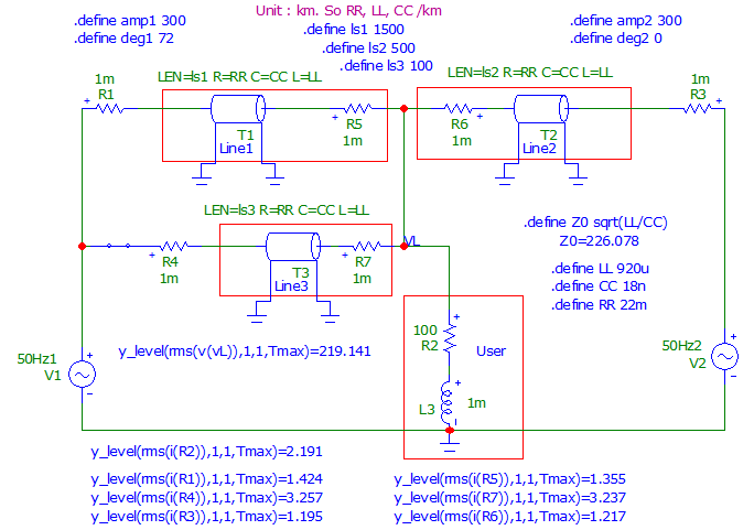
Added resistors at the Load location to measure currents at the outputs of the lines (RMS values).

enter image description here

\$\endgroup\$
1
  • \$\begingroup\$ "This can't receive an answer if you don't know all the characteristics of the "whole" network" I disagree, the question could be re-stated as "how can any electrical grid operate with loops". I don't understand the rest of the answer enough to know if that was answered. \$\endgroup\$
    – Shelvacu
    Commented Nov 6 at 1:44
4
\$\begingroup\$

Essentially it’s more or less self-regulating - if one generator has a tendency to run fast then it will be more heavily loaded as it’s output voltage tends to lead each phase. In contrast a slow-running generator will be more lightly loaded and ultimately could be actively driven by grid power. Where multiple paths of different lengths exist there could be losses, which could be visualised as current going round a loop rather than supplying a consumer. To bring a generator online you’d sync with the local grid frequency and phase, then close the breakers.

\$\endgroup\$
2
  • 10
    \$\begingroup\$ I believe the question is about transmission-line delay clashes rather than getting a generator in sync. \$\endgroup\$
    – Andy aka
    Commented Sep 4, 2022 at 7:18
  • \$\begingroup\$ Possibly so. To address that, transmission lines are notoriously inductive, with current trailing voltage by 70 degrees in some cases. I know that large capacitors are sometimes used to attempt to correct this, and that approach could conceivably be used to reduce the phase differences. \$\endgroup\$
    – Frog
    Commented Sep 4, 2022 at 11:18
4
\$\begingroup\$

Two sources may help answerr this to some extent.

[1] An article on the 'Scientific American' website discussed this issue in June 1998: "How is electricity from different generators synchronized so that it can be combined to service the same grid?"

The aricle gives some information, though not full information, I think. It does imply that there is a degree of automatic (phase) alignment through the magnetic fields associated with each generator.

Also given is the information that "In high-voltage transmission lines (those over approximately 100 kilovolts), [the] inductive impedance is greater than the effect of resistance by at least a factor of 10 and more likely, 20", and that there are phase delays, "that is, the receiving-end voltage lags behind the sending-end voltage". Also, at switching stations, "measurements such as voltage and voltage phase angles are made. For power to flow on the network or grid, each bus must be somewhat out of phase with other buses."

But the article does not explain, for example, what is done with those measurements. So while that article goes perhaps a little further than the information on here so far, it probably is not complete enough to satify the questioner.

[2] Then L Teschler (2019), 'How AC Power Sources Get Synchronized', says that "When a generator" {i.e. one of many in an a.c. grid} "is powered down for maintenance or even temporarily disconnected, it must resynchronize upon rejoining the grid, generally by automatic means with manual backup instrumentation in place if needed." Specifically, a generator about to be connected "must match {the grid} in voltage, frequency, phase, and phase sequence. And, of course, they must both be sine waves. In the case of phase, “synchronization” is defined as being within one electrical degree of the grid phase."

Synchronization is established with the individual generator still electrically isolated. Another requirement for ac synchronization of rotating generators is that generators added to the grid must have the proper droop speed (that is the difference between rated rpm and actual speed) so the shared load is in correct proportion to their respective ratings. The droop speed applies to the prime mover. This is a necessary requirement because the loading of a generator reduces its speed, which in turn precisely determines the frequency. It is possible for generators connected in parallel to rotate at incrementally different speeds because the output frequency of each is also a function of the number of poles.

To synchronize a single a.c. generator into an operating network, one must manipulate the new unit so its voltage and frequency are a close match to the overall network. Then the generator can be electrically connected. When connected, it will automatically lock onto the larger network and thereafter maintain synchronization without further adjustment. When a single small generator connects to a larger grid, every constituent generator changes its frequency output slightly to accommodate the added member, which adjusts to a far greater degree.

There are over 500 individual utilities supplying the North American grid, some having extensive banks of generators, all synchronized. The grid is divided into several segments, connected by high-voltage d.c. links, obviating the need for these large a.c. segments to synchronize with one another.

The article mentions the circuit breakers through which the units connect, and their ability to act quickly to prevent the damages that might occur through mismatch.

It also describes a very old manual matching method used in the early days of a.c. 3-phase power networks, which used to use triples of incandescent lamp bulbs as phase indicators; and a slightly more recent manual matching method using a "synchroscope". Further, --

Fully automatic synchronization originally depended upon electromechanical synchronizing relays. Currently, highly reliable microprocessors have taken over, although lamps and synchroscopes remain in place for monitoring and backup purposes.

A synchro check relay is inserted as an added precaution. It operates automatically to prevent interconnection in the event of excessive phase error.

All machines remain synchronized when the load changes within specific limits. An excessive change in system frequency, however, can cause constituent members to fall out of synch. Automatic disconnection then takes place, and this can cause a temporary power outage until the machines resynchronize.

For feeding renewable energy into the supplies in synch:

Renewable energy sources generate power via inverters that convert dc from, say, a solar array ... In the case of wind turbines, the turbine powers an ac generator whose frequency varies in proportion to wind energy. This varying frequency is generally converted to dc and then to constant-frequency ac that is grid compatible.

Of course, the connected ac must be synchronized to the grid. This takes place by means of a special kind of inverter called a synchronous inverter. Unlike an ac generator that is synchronized with another generator or into the grid, the synchronous inverter continuously samples the utility ac and synthesizes an output to match, copying the utility waveform with regard to voltage, frequency and phase angle.

The synchronous inverter is complex but the price has dropped as increasing numbers of units are sold.

\$\endgroup\$
2
\$\begingroup\$

I think the basic answer is just that what look like loops on your map are not actually loops. The lines coming into a power station don't need to be tied together in a single circuit.

When a station receives power from multiple sources, it divides its customers between the sources and switches them from one to the other as necessary.

\$\endgroup\$
1
  • \$\begingroup\$ This configuration is possible, but I don't think it is normal if you are looking at the high voltage transmission network as in the original question. Usually only the distribution and sometimes the sub-transmission system is operated (approximately) radially. The transmission system is operated in a mesh configuration with rare exceptions. Mesh operation increases the reliability and capacity of the system. \$\endgroup\$
    – pdb5627
    Commented Sep 6, 2022 at 19:47

Your Answer

By clicking “Post Your Answer”, you agree to our terms of service and acknowledge you have read our privacy policy.

Not the answer you're looking for? Browse other questions tagged or ask your own question.