1
\$\begingroup\$

I'm very new to the study of power grids and I'm having some trouble understanding some very basic concepts.

I have been looking at the problem of synchronisation on power grids and I'm not quite sure what a `phase' represents. Is there a reason that loads/consumers in a power grid are always treated as rotating machines (motors)? Also, when the equations refer to a phase do they mean the AC phase or the phase of generator/motor rotor? Are these the same thing?

Also another point of confusion is about power transmission. The first paragraph of the Wikipedia page, Synchronization (alternating current) says that

If two unconnected segments of a grid are to be connected to each other, they cannot exchange AC power until they are brought back into exact synchronization.

However this seems to be contrary to what I've read in papers such as this and this, which say that power transmitted, \$P_{\text{trans}}=P_{\text{max}}\sin(\theta_1-\theta_2)\$ meaning that power would not be transmitted if the phases are the same.

I think the problem is that I'm mixing up different concepts here. Any references for this subject would be greatly appreciated!

Edit: I thought I should summarise all the questions I'm asking here:

  1. Why are loads modelled as motors?
  2. Are the phases the phase of an AC sin wave or the angle made by a rotor (of a generator or motor)? Are these phases just the same thing and if so, why?
  3. When is power transmitted maximum--- when phases are the same or different?
\$\endgroup\$
1
  • \$\begingroup\$ This is a large question actually formed of multiple questions around a topic. An answer to all of it will need to be quite large. You may get clearer answers if you posted the 3 or 4 questions as separate ones. See how you go with the answers you get I suppose. \$\endgroup\$
    – TafT
    Commented Jul 22, 2021 at 10:41

4 Answers 4

4
\$\begingroup\$

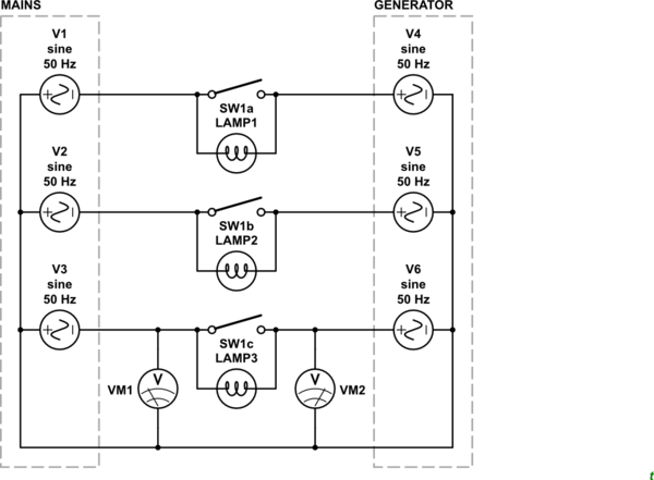
I learned a little of connecting three-phase generators to the grid in a class in university many decades ago. The setup was a mains connection, three-phase contactor, some lamps and a generator which was driven by a DC motor.

schematic

simulate this circuit – Schematic created using CircuitLab

Figure 1. Three-phase synchronisation class.

Procedure:

  • Start the generator. (In our case we adjusted the field current of the DC motor driving the generator.)
  • Using a frequency meter adjust the generator speed to get close to 50 Hz.
  • LAMPs 1 to 3 would blink at the "beat" frequency, fmains - fgen. When our generator was very close to synchronised the lamps would fade in and out very slowly.
  • Adjust the generator voltage to match the mains voltage: VM1 = VM2.
  • Wait for the phase lamps to go dark and close SW1. If this is done correctly there will be no arcing and no significant current will flow.

We were then able to increase the power into the generator motor and observe that while everything remained in synchronisation that power would flow from right to left as our little generator tried to speed up the whole of the Irish national grid (which, of course, it couldn't).

We could also reverse the drive on the generator motor so that it acted as a brake to the generator. Under these conditions the power would flow from left to right as the national grid tried to keep the generator in sync (which it was able to do).

There's a demo on YouTube, Synchronizing AC generators -- Part 1 (introduction and sync lamps) that demonstrates this but he's using little neon indicators. We used lovely 60 W lamps so the effect was much more impressive.


To answer your specific questions:

  1. Why are loads modelled as motors?

They're not. Resistive and capacitive loads are fine too.

  1. Are the phases the phase of an AC sine wave or the angle made by a rotor (of a generator or motor)? Are these phases just the same thing and if so, why?

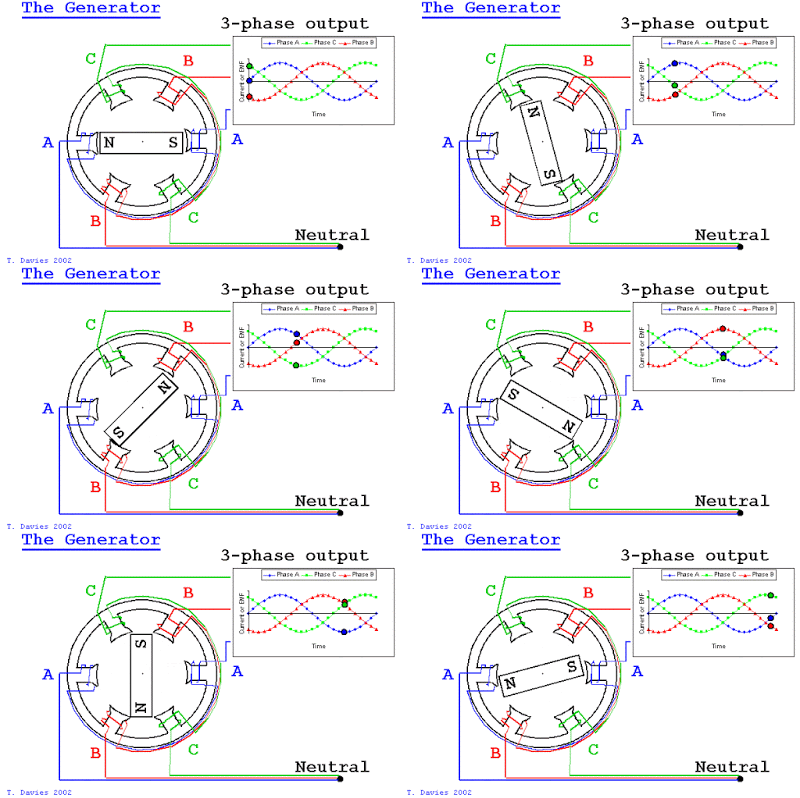
(Simple version.) The three coils of the generator are 120° apart. The voltage of each one goes positive and negative as the north and south poles of the rotor pass by. The result is that the three phases are 120° out of phase too.

enter image description here

Image source: https://www.quora.com/Why-do-we-have-three-phases-in-an-alternator-and-not-a-single-phase.

  1. When is power transmitted maximum--- when phases are the same or different?
Once connected the phase of the two systems has to be identical. Each of the generators will be helping to the grid with the units "pedaling harder" contributing more. You could consider it like a tandem bike where the total effort in propelling the bike is the sum of the individual efforts. They can contribute equally or one can be taking a free ride with the other doing all the work.

enter image description here

Figure 3. Unequal power generators in perfect synchronisation. Image source: Chicago Tribune.

\$\endgroup\$
2
  • \$\begingroup\$ Great picture as an analogy for unequal gensets being synced. \$\endgroup\$
    – David777
    Commented Jul 22, 2021 at 10:56
  • \$\begingroup\$ Thank you, this is a great answer. \$\endgroup\$
    – sobol
    Commented Jul 22, 2021 at 14:53
4
\$\begingroup\$

The phases really are the phases of the sine waves. Traditional generators are rotating machines with three outputs.

If we let one of those phases be defined as sin(t), then the others are sin(t + 120°) and sin(t + 240°).

If you plot that as a graph, you get three sine waves, all 120° out-of-phase with each other.


There's no reason to assume that loads are motors. They could easily be resistors, and it's often assumed that they are. Resistive loads give better power transfer than ones that are capacitive or inductive.


If you're trying to connect two parts of a broken grid, or simply re-connect one generator to the grid, then they really need to be almost exactly in phase. If they are out of phase, then plenty of power transfer will occur - and shortly after, something will go 'bang'. You're connecting two very low-impedance voltage sources in parallel, and if they are not in phase, then the voltages at any given moment will be completely different.

\$\endgroup\$
1
  • 1
    \$\begingroup\$ "There's no reason to assume that loads are motors" I think it is less about assumption and more that in situations that matter large single or multip-phase motors are the big problems you have to solve in power distribution. Simple pure-resistive loads don't need much thought but indictive or capacitive loads have to be accounted for on a single phrase / branch. \$\endgroup\$
    – TafT
    Commented Jul 22, 2021 at 10:37
3
\$\begingroup\$

Generators have 3 windings that produce power 120 degrees apart - think rotating machine and 360 degrees in a circle.

Each winding is known as a phase, often labelled red, yellow and blue or red, white and blue, just depends on the country.

Many countries supply a street with 3 phase and each house gets a single phase supply using each one in turn to "balance" the load.

Some countries supply all houses with 3 phase - just the power varies.

Instead of your link try this one: https://en.wikipedia.org/wiki/Three-phase_electric_power

\$\endgroup\$
2
  • \$\begingroup\$ Thanks for the answer. My question was more about what \$\theta\$ means in these equations. Does it represent the phase of the AC sin wave or does it represent the physical angle made by the rotors of the load/generator? \$\endgroup\$
    – sobol
    Commented Jul 21, 2021 at 17:59
  • \$\begingroup\$ @sobol well I started with "phases" as you need to be sure of what you are talking about before going further... \$\endgroup\$
    – Solar Mike
    Commented Jul 21, 2021 at 18:00
3
\$\begingroup\$

This answer only talks about phase as the relative electrical phase between two segments. See other answers for the meaning of 'phase' as one of the three conductors of a 3-phase system.

If two unconnected segments of a grid are to be connected to each other, they cannot exchange AC power until they are brought back into exact synchronization.

Exact synchronisation here has to start with getting the two segments to run at the same frequency. Once they are at the same frequency, you can define a phase difference between them.

If you simply connect them at that point, with some arbitrary phase diffence, then the power that flows between them may be very high, unsafe for the transmission lines. The quote means 'they cannot safely exchange AC power'.

The last stage of synchronisation before connecting them would then to be bring the phases equal, or close enough that little power would be transferred.

Once connected, then power can be shifted between the two segments by adjusting the relative driving power of the two, which as a by-product changes the phase between the two. Increasing the driving power advances the phase of one with respect to the other, and so exports power.

\$\endgroup\$
3
  • \$\begingroup\$ Thank you, this was very helpful. Could you also comment on why it is reasonable to model the consumer end as something that is rotating? When I think of the power grid, I tend to imagine a generator at one end (which is clearly rotating), but at the consumer end, I think of something like a lightbulb and it's not clear to me what exactly we are trying to synchronise here. \$\endgroup\$
    – sobol
    Commented Jul 21, 2021 at 18:36
  • 1
    \$\begingroup\$ We're not trying to synchronise to anything at the consumer end, it synchronises to the grid. When we're synchronising different segments of the grid, it is still the case that almost all the generating capacity is rotating, and if there's power flowing from one to the other you can consider one side as a generator and the other as a motor, at least differentially. \$\endgroup\$
    – Neil_UK
    Commented Jul 21, 2021 at 19:02
  • 1
    \$\begingroup\$ @sobol there's a surprising amount of consumer motors on the grid as well; I heard something like half of electrical power being used to power motors (but I heard this in a motor promo video, so it's a bit biased). Nevertheless it's the motors jobs to synchronise themselves to the grid... But also yes phase does literally mean the (electric) angle of the electric motors. But motors can have more than 3 poles so the physical angle is an integer multiple of the electric angle, depending on the construction of each motor. \$\endgroup\$
    – csiz
    Commented Jul 22, 2021 at 4:24

Your Answer

By clicking “Post Your Answer”, you agree to our terms of service and acknowledge you have read our privacy policy.

Not the answer you're looking for? Browse other questions tagged or ask your own question.