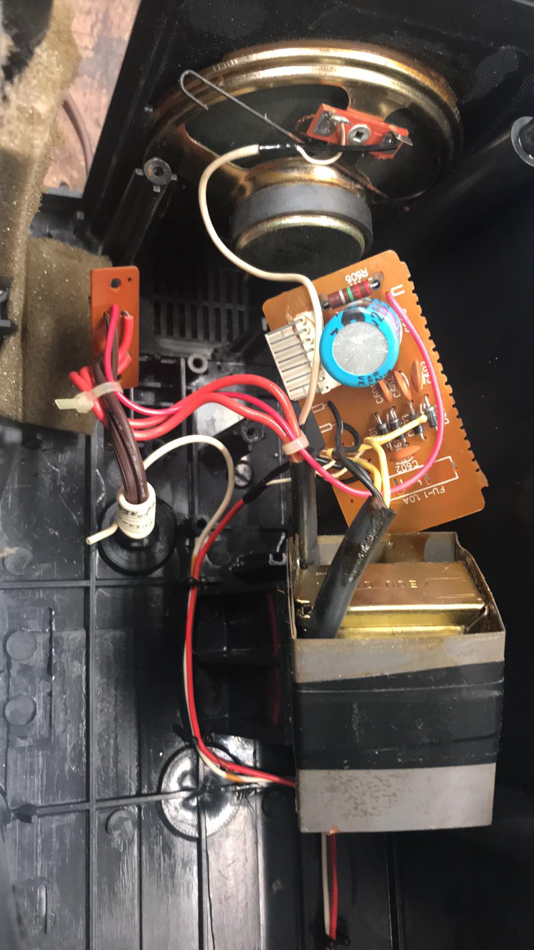
I have been working on electronics for over 35 years and never seen anything like this. While going to repair a JC Penney AM/FM Stereo/Cassette/Clock Radio Model 680-3796 Catalog # 850-1793 FCCID:ANV9UD680-3796 which only has sound out the right speaker, I connected my oscilloscope to a leg of the left speaker that has no output and saw 120 VAC, 60 Hz. I unplugged the radio and when inspecting the bridge rectifier board saw that they designed the clock radio to have a 2.2 MΩ Allen-Bradley 1 Watt 20% resistor tying 120VAC to the common of the DC side of the bridge rectifier. This connection to common through the 2.2M resistor makes everything inside the radio float on 120VAC.
I am tempted to clip this resistor out to remove this stupid floating 120 VAC but before I do so I figured I would ask someone who is more knowledgeable than myself as to if it has a required purpose or not for the filtration somehow as to me it makes absolutely no sense to have your secondary side of a transformer with the bridge rectifier tied to 120VAC Main through a 2.2 MΩ resistor. The red wire that runs from main power from a strange small daughter board to around back side of 2200 uF, 25 V cap to leg of 2.2M resistor of the filtered bridge rectifier board is where it gets its 120 VAC. In the hundreds of radios I have repaired I have never once come across something so odd. It was only with old tube sets and non polarized plugs that you had to ever worry about a floating 120 VAC inside a radio and this is all 1982 technology with mostly analog components as it was manufactured October 1982. Normally your secondary from transformer is isolated from primary side mains and you have a nice filtered DC output from the bridge and its filter caps.

