1
\$\begingroup\$

I've a big 3000 F 6 x supercapacitors bank to work as an aux USB power hub. It gives power while linearly losing voltage to 5 V, then it stops working, because I'm using a 5-15 V to 5 V DC/DC converter. However, it still has loads of power left below 5 V, and I need to boost the remaining voltage to 5 V.

It's not easy to find a DC/DC converter which gives a constant 5 V (output power up to 25 W), and uses 1-15 V input.

So I've decided to use a 1-5 V -> 5 V boost converter and a 5-15 V -> 5 V buck converter, with an automatic switch using an optocoupled relay controlled by a 5.4 V Zener diode.

However, I don't like this solution, because the relay itself draws some current (like 50 mA) and is not reliable, as it is a mechanical device.

What is a more elegant solution?

Like a more efficient buck/boost switch of 1-15 V -> 5 V buck/boost converter available on market, or an electronic schematic which can be soldered easily (no small parts).

\$\endgroup\$
7
  • 4
    \$\begingroup\$ Note that at 5V, there's only about 10% energy left in the capacitors, and going down to 1V at that power isn't going to happen (you'd need to draw well over 25A!). Trying to extract more energy may simply not be worth it. \$\endgroup\$
    – marcelm
    Commented Oct 2, 2022 at 15:09
  • \$\begingroup\$ Buck-boost or live with the limitation. \$\endgroup\$
    – winny
    Commented Oct 2, 2022 at 15:49
  • \$\begingroup\$ When you say "soldered easily (no small parts)" I assume that you mean no through-hole parts. The world has gone over to surface mount so you're not making things easy here. \$\endgroup\$
    – TimWescott
    Commented Oct 2, 2022 at 15:53
  • 1
    \$\begingroup\$ @winny: topologies that put the positive end of the caps on ground, or the negative end on +5V would work. They'd look like boost or inverting topologies, sorta, but you could get by with one switch and no mode changes. Trying to do it with through-hole would probably mean no synchronous converters, and thus less efficiency than just discharging the caps down to 5V using a synchronous buck. \$\endgroup\$
    – TimWescott
    Commented Oct 2, 2022 at 15:59
  • 1
    \$\begingroup\$ You'd want to use either a SEPIC or a four-switch buck-boost, I imagine. LT, Maxim, and TI all make good controllers for both topologies. \$\endgroup\$
    – Hearth
    Commented Oct 2, 2022 at 16:25

2 Answers 2

1
\$\begingroup\$

Getting all the way down to 1 V is going to be difficult, but there are some converter topologies that can do what you want. You might just have to cut off at 1.5 or 2 V instead of 1 V.

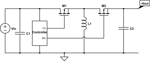
First and most basic is the conventional buck-boost converter, like so:
schematic

simulate this circuit – Schematic created using CircuitLab

The downside to this one is that Vout is restricted to being negative, if the input is positive. If the input is negative, you can move things around a bit and get a positive output. But the input and output have to be opposite polarity. If that's not a problem for you, this will work. If that is a problem for you, there are two other topologies that come to mind.

The SEPIC is a relatively complex topology, especially to analyze, but controllers for it are readily available from major manufacturers. (However, it may be difficult to find synchronous SEPIC controllers.) It can output voltages higher, lower, or the same as its input. Most any buck converter controller can be used for a buck-boost converter, if some level shifters are used.

schematic

simulate this circuit

As synchronous SEPIC controllers are so rare, I've shown a non-synchronous one here. A synchronous one would replace D1 with a second MOSFET.

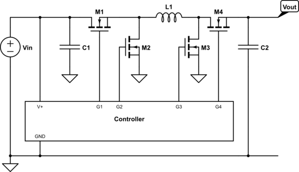
If you want the higher efficiency of a synchronous converter, or you just don't want to deal with the multiple inductors or difficulty of analyzing a SEPIC, you could use a four-switch buck-boost. This is essentially just a standard buck converter and a standard boost converter sharing the same inductor:
schematic

simulate this circuit

When the input is significantly less than the desired output, M1 is held on, M2 is held off, and M3 and M4 switch like a normal boost converter. When the input is significantly greater than the desired output, M4 is held on, M3 is held off, and M1 and M2 switch like a normal buck converter. The transition between the two modes, when the input is approximately equal to the desired output, sees all four switches actively switching.

This type of converter requires more active switches than the other types, and the controller may be more expensive, but it's a fairly straightforward way of doing what you want.

\$\endgroup\$
0
\$\begingroup\$

Since the additional energy you might get out represents only 10 % or so of the capacitor's storage, it may not be worth doing as it may degrade the overall efficiency of the primary buck mode by more than 10 %.

\$\endgroup\$

Your Answer

By clicking “Post Your Answer”, you agree to our terms of service and acknowledge you have read our privacy policy.

Not the answer you're looking for? Browse other questions tagged or ask your own question.