4
\$\begingroup\$

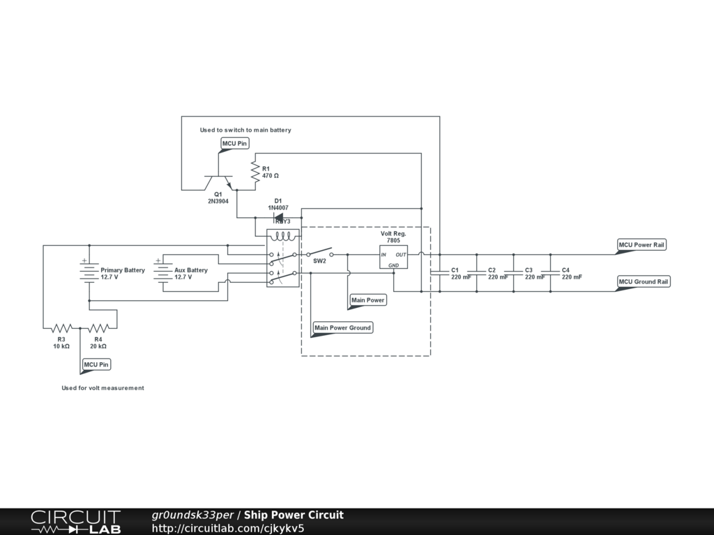
I am building a model warship that needs 12 volts and 5 volts to run its motors and a microcontroller. The ship is powered by two 12 volt lead acid batteries wired in parallel. I built a power board that, among other things, splits the battery between power out (which will connect directly to the motor controllers) and a LM7805 volt regulator. I am worried that when the motors (three total) are run at the same time, this will cause a power drop below the regulator's usable threshold. Is there a way to ensure the regulator receives enough power?

schematic

\$\endgroup\$
3
  • 1
    \$\begingroup\$ What is the current draw of the motors, and capacity of the battery? \$\endgroup\$
    – Matt Young
    Commented Apr 1, 2013 at 15:56
  • \$\begingroup\$ The batteries are both 6.5 amp hour. The combined motors will be about 5 amps. \$\endgroup\$ Commented Apr 1, 2013 at 17:18
  • \$\begingroup\$ @groundsk33per It's usually good form to wait at least a day before accepting an answer, to give others incentive to provide answers. You may upvote as many answers as you see fit, but can only accept one. \$\endgroup\$ Commented Apr 1, 2013 at 18:07

2 Answers 2

2
\$\begingroup\$

I assume your microcontroller circuit does not need much current (~ 100 mA), so a linear regulator (7805 style) will not get too hot. If not, consider a switching regulator.

Using a low-dropout regulator will reduce your problem a lot, as the Photo pointed out.

If your problem is very short surges a simple capacitor will help.

If the surges are a bit longer you could add a (schottky) diode before the capacitor, so a drop in the motor voltage will not immediately cause a drop in the regulator input.

some more points:

  • There is no need to switch both legs of the battery contacts: connect the grounds together, and switch only the positive legs.

  • If you measure the voltage after the switch you can use the same circuit to monitor the battery voltage of the secondary battery too (when it is active).

  • the choice of resistors in the voltage monitor part is wrong (probably reversed?). As is, you get 2/3 of the power voltage, 1/3 seems better (although personally I would allow for some headroom and choose 1/5 or even 1/10. You are not into high-accuracy measurements here.) and add some capacitor to smooth out peaks.

  • your relais drive uses an emitter-follower. I suggest you use a the more standard common-emitter style switch, and feed the relais from the primary battery. This will lower the load of the 5V (and on the battery, because a 12V relais uses less current). But maybe use an 9V relais, to prevent unwanted switchover during a power drop.

\$\endgroup\$
3
\$\begingroup\$

A 7805 should be able to regulate 5 V so long as you keep the input above 8 V or so. Dropping a 12 V battery to 8 V sounds like quite a drop to me, but I don't know the full parameters of your batteries, etc.

Supposing that a drop below 8 V is possible, the easy solution is to find a regulator that doesn't need so much drop-out. There are low drop-out regulators that can regulate 5 V with inputs as low as 5.3 or 5.5 V. The trick will be finding one that can also handle the power needed to regulate 5 V when the input is as high as 12 V. Since you haven't mentioned the amount of current being sourced, I can't say whether this will be a problem or not.

A less easy but much more efficient solution would be to use a switching regulator. A buck regulator could probably be found that will be able to regulate 5 V with inputs between, say 6 and 24 V (obtaining good performance with very wide range of input voltages may require some careful design and design trade-offs). These can even be found with physical size and pin assignments designed as direct replacements for the 7805. A buck regulator will also dissipate much less heat than the 7805 when the battery voltage is high, so this could save you in other ways.

Finally, if you think the input voltage might dip below maybe 5.5 V, and you want the efficiency of a switching regulator, you can look at buck-boost circuits. A buck-boost could conceivably generate your 5 V mcu power supply given an input voltage anywhere from 1.2 to 12 V.

The details of choosing or designing any of these circuits requires knowing the range of currents your circuit will draw, and the range of input voltages you need to accomodate.
\$\endgroup\$
1
  • \$\begingroup\$ Thanks for the informative feed back! I'm going to build a prototype and see how much of a drop I can make. I'm going to stick with the linear regulator right now due to cost and availability (I'm up to my ears with these things). \$\endgroup\$ Commented Apr 1, 2013 at 17:24

Your Answer

By clicking “Post Your Answer”, you agree to our terms of service and acknowledge you have read our privacy policy.

Not the answer you're looking for? Browse other questions tagged or ask your own question.