1
\$\begingroup\$

If we have two lamps, two switches and two batteries, how do we wire them up in a way that switching one of the switches makes it impossible for the other to work? I am experimenting in tinkercad, but so far no luck.

Edit: I was allowed to edit the question in order to clarify that switch A should not affect lamp B and switch B should not affect lamp A. In other words: Switch A should be off for circuit B to work and Switch B should be off for the circuit A to work. The first switch to be on, makes its lamp on and disconnects the other circuit. This is used as a way to measure who turns the switch faster without using digital logic or complicated/expensive electronics i.e it's noob-friendly.

\$\endgroup\$
4
  • 4
    \$\begingroup\$ Easy if one switch is SPDT. \$\endgroup\$ Commented Nov 12, 2022 at 23:58
  • 1
    \$\begingroup\$ What you're looking for is a game-show buzzer circuit, that detects which button was pushed first? \$\endgroup\$ Commented Nov 13, 2022 at 20:38
  • \$\begingroup\$ @KenShirriff I don't know for the "game-show" part, it's for training purposes, but yes. The first player-specific-colored lamp to glow indicates the player was faster and the other circuit is then disabled until switched off in order for it to be detectable. I heard somewhere before that it is possible to achieve this via a trick with switches. It is possible that I missed a usage of something else, but it was super simple in overall \$\endgroup\$
    – Edenia
    Commented Nov 13, 2022 at 21:11
  • \$\begingroup\$ I doubt you'll find anything that doesn't somehow involve a pair of relays or transistors or other devices. Essentially letting one switch override another. A pair of relays done right is really very simple - 100 year old technology. \$\endgroup\$ Commented Nov 13, 2022 at 23:37

5 Answers 5

9
\$\begingroup\$

schematic

simulate this circuit – Schematic created using CircuitLab

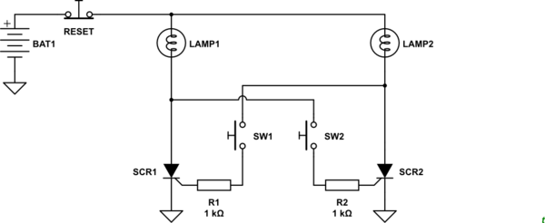
Figure 1. The two-lamp priority circuit.

Thyristors have the odd characteristic that once switched on they remain on until the current through them falls below the holding current. We can use this to turn on the lamp of the first button to be pressed and inhibit the other.

How it works:

  • Initially both lamps are off. LAMP1 provides battery voltage to SW2 and LAMP2 provides battery voltage to SW1.
  • Pressing SW1 will trigger SCR1 causing it to turn on. LAMP1 will light.
  • When SCR1 turns on the voltage at the lower terminal of LAMP1 will drop from V+ to a voltage close to ground. This means that if SW2 is now pressed that SCR2 will not be triggered (because the gate voltage is too low) and LAMP2 will not turn on.

Pressing the RESET button will reduce the current through either SCR to zero ready for the next round.

\$\endgroup\$
6
  • \$\begingroup\$ No relay dead time without winner decision, best solution. \$\endgroup\$
    – Jens
    Commented Nov 13, 2022 at 16:44
  • \$\begingroup\$ That looks promising! Something like that was in my mind too, unfortunately I cannot make a simulation in tinkerkad due to the lack of support for thyristors. There was a professional software that could do that and everything else, but I forgot its name \$\endgroup\$
    – Edenia
    Commented Nov 13, 2022 at 19:42
  • \$\begingroup\$ @Edenia, was it LTSpice? You can try it on Tinkerkad using transistors. They just won't latch and the light will turn off when you release the button. \$\endgroup\$
    – Transistor
    Commented Nov 13, 2022 at 21:11
  • \$\begingroup\$ @Transistor Ah the light should stay until pressed again, for best results. To be honest now that I think of, it is not a huge restriction per se.. But push buttons and transistors sounds like something cheaper than Arduino, but also relatively simple so it is in the middle \$\endgroup\$
    – Edenia
    Commented Nov 13, 2022 at 21:14
  • \$\begingroup\$ For the transistor version you could make the rule that they have to hold the button until it's clear who pressed first. If the second person holds their button and the first lets go then the second person's light will turn on. \$\endgroup\$
    – Transistor
    Commented Nov 13, 2022 at 22:20
6
\$\begingroup\$

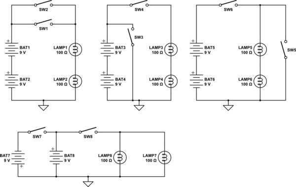
All these circuits fulfill the requested condition. Closing an odd numbered switch prohibits, that closing the even numbered switch has any effect on the lamps.
The first circuit may be useful, but don't try the others with real world components, batteries and switches will be destroyed.

schematic

simulate this circuit – Schematic created using CircuitLab

EDIT: This circuit meets more detailed requirements mentioned in comments.

schematic

simulate this circuit

\$\endgroup\$
14
  • \$\begingroup\$ Yes but, on the first circuit, doesn't the switch light up both lamps though? It almost works, but wouldn't the switch affect both lamps? \$\endgroup\$
    – Edenia
    Commented Nov 13, 2022 at 2:38
  • 1
    \$\begingroup\$ @Edenia I assumed something like this, but you must mention such constraints in your question. I hope you will forgive me this kind of engineering humor. \$\endgroup\$
    – Jens
    Commented Nov 13, 2022 at 2:48
  • 2
    \$\begingroup\$ @Edenia I guess this will involve some 1 bit memory, a flipflop or a relay trick. I will expand my answer if I am inspired. There are some similar questions/circuits here on this site. I will link them if I find them again. \$\endgroup\$
    – Jens
    Commented Nov 13, 2022 at 3:06
  • 2
    \$\begingroup\$ @Edenia Please edit the original question in a way, that it includes all requirements. Questions and answers must match without reading all comments. \$\endgroup\$
    – Jens
    Commented Nov 13, 2022 at 3:54
  • 2
    \$\begingroup\$ @Jens, I built that last one in 1978 for a "game show" in my high-school's auditorium. Only, mine didn't lath, and it needed no reset button. I simply required contestants to hold their button long enough for the judge to acknowledge. I think the cost of a reset button would have broken the budget. My partner and I promised to build the whole thing, including wooden panels to which the buttons and lamps were mounted, for less than $20 USD. As an additional cost-cutting measure, and because we needed lights bright enough for the audience to see, we used mains-voltage throughout. :-O \$\endgroup\$ Commented Nov 13, 2022 at 17:55
4
\$\begingroup\$

You have \$N=2\$ switches (inputs), meaning that there are \$2^N=4\$ possible combinations of switch positions.

Before proceeding to tinker, it's best to formally define the lamp states that would result for each input condition, in a table:

Switch 1 Switch 2 Lamp 1 Lamp 2
Open Open
Open Closed
Closed Open
Closed Closed

Fill in columns 3 and 4, and then you can proceed.

As it stands, we are being asked to guess what "one lamp disables the other" actually means. This implies some symmetry to the problem, but if you think about it, one of the lamps will need priority in the case where both switches are on. Otherwise the system would have to have some form of "memory" of prior states. This suggests a fundamental asymmetry entirely absent from your description of it, which would become immediately clear if you formally described behaviour in the truth table.

What also becomes clear when you write out a truth table, is if the problem even has a solution using simple passive and combinatorial elements. It's unlikely to be an issue in this case, but the argument for a formal statement of input vs. output requirements is still strong. By forcing yourself to imagine the state of affairs for every single input condition, you must necessarily become aware of practical logical flaws.

Also, you say you want to use two batteries, implying that there is some independence between each set of "battery+switch+lamp", but almost every case in that table is possible to implement with a single voltage source. It's therefore also necessary for you to explain to us the reason for having two independent power sources. Without this information it is impossible to guess how they should interact, whether it's OK for one single battery to power both lamps, and so on.

You have not stated if it's OK to use relays, or transistors in the solution. Perhaps you wish to use purely passive elements, namely switches, lamps and batteries, or perhaps you are willing to consider active parts.

In short, your question is vague, and can't be answered in its current state.

\$\endgroup\$
1
  • \$\begingroup\$ You should read the additional comments by the OP and see the other answers that seem to provide what was asked for. But the OP should add those comments to the question, and one of the answers should be accepted. \$\endgroup\$
    – PStechPaul
    Commented Nov 13, 2022 at 8:03
2
\$\begingroup\$

schematic

simulate this circuit – Schematic created using CircuitLab

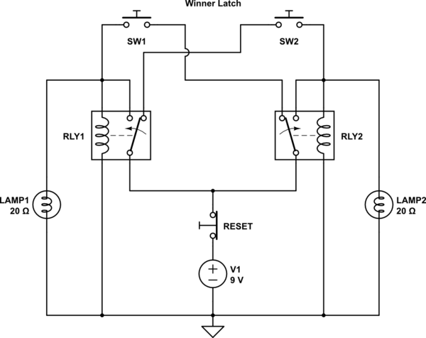
I think this will work to detect the first button press. I forgot to add lamps across the relay coils.

\$\endgroup\$
2
\$\begingroup\$

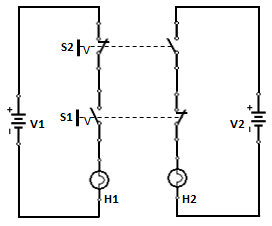
Version 1

enter image description here

Version 1 does not satisfy the requirement (Refer PStechPaul's comment)

Version 2

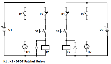
Using two DPDT Ratchet relays

enter image description here

Operation:

  1. Actuating S1 latches K1, turns on H1 and disables H2 circuit.

  2. Actuating S1 again resets K1, turns off H1 and enables H2 circuit.

  3. Now actuating S2 latches K2, turns on H2 and disables H1 circuit.

  4. Actuating S2 again resets K2, turns off H2 and enables H1 circuit.

\$\endgroup\$
2
  • 1
    \$\begingroup\$ If switch S1 (bottom) turns on lamp DS1 (left), then switch S2 (top) can turn it off. \$\endgroup\$
    – PStechPaul
    Commented Nov 13, 2022 at 9:02
  • \$\begingroup\$ @PStechPaul - Hi Paul, Thank you very much for pointing it out. I have edited my answer. \$\endgroup\$
    – vu2nan
    Commented Nov 13, 2022 at 11:18

Your Answer

By clicking “Post Your Answer”, you agree to our terms of service and acknowledge you have read our privacy policy.

Not the answer you're looking for? Browse other questions tagged or ask your own question.