1
\$\begingroup\$

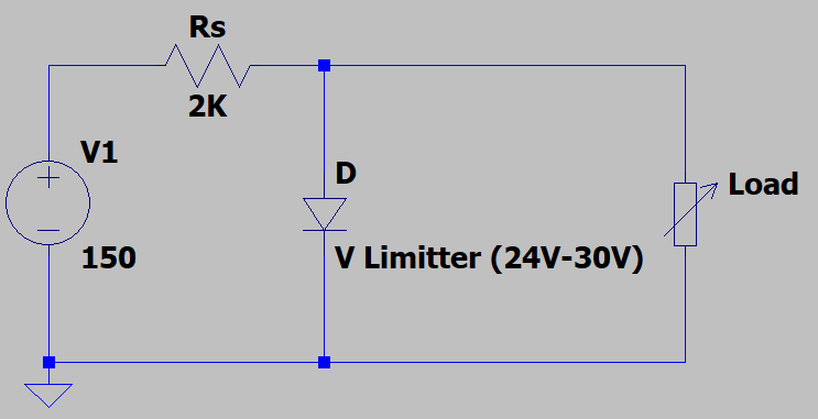
I want to power supply a board (variable load 1.6 W at 24 V) from a 150 VDC source (rectified AC line) through a 2 kΩ, 20 W series resistor.

Due to mechanical arrangement of the equipment the only available access is the second terminal of the 2 kΩ resistor and GND. No access to the main supply is possible. All needed power must be drawn from the supply through the 2 kΩ resistor (max 75 mA). The board can be simplified as three bucks (24 V to +10 V/+5 V/-10 V) each supply many devices.

enter image description here

Since the current is limited by the 2 kΩ source resistor, the board won't start operating because it needs a surge current at start-up (due to the large input capacitance). One could say a soft-start should be considered after reaching the desired voltage bucks can be enabled to operate. Good point, but the board could not be redesigned.

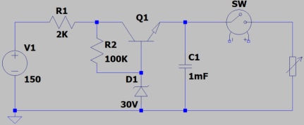
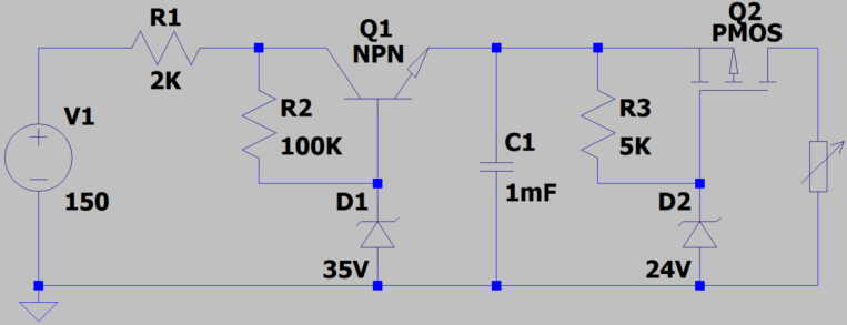
So, I came up with external circuitry to store sufficient energy in a large capacitor. After reaching the target voltage the energy should be released fast enough to the load. I tested the concept by connecting the board manually when the voltage across C1 is regulated through Q1D1 LDO. It works!

enter image description here

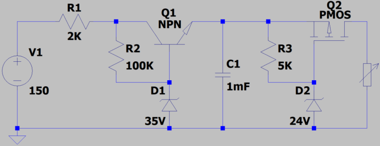
Where I got stuck is with making a fast switch to release the stored energy. I have tested the following circuit, but the board won't start; I think because it turns on slowly.

enter image description here

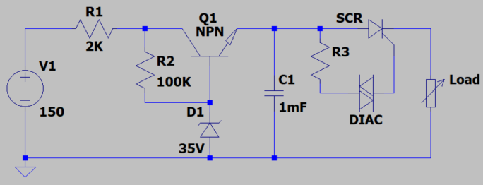
The second solution I considered is to use an SCR and a DIAC to connect the load after reaching the voltage threshold. The problem with this configuration is that if the source drops enough to power off the board, but is still delivering a small amount of current, the SCR stays ON and after the source reaches the nominal voltage again the boards won't restart operating (voltage divider between source resistor and load).

enter image description here

Maybe the fast solution is to use a comparator with a push-pull output and fast slew rate to drive the PMOS (1st solution) fast enough. It will be also easier also to define thresholds voltages by monitoring the source voltage to open and close the P-MOS switch.

I am looking for a simple solution with hand wired elements (1206, 0805, SOT23, SOT228, SOD80...). Any idea to suggest, even if it is for a complete solution, not only the switch?

\$\endgroup\$
7
  • 1
    \$\begingroup\$ Why can't you use a comparator (non discrete component)? You will need hysteresis and a comparator should not be excluded without a really valid reason. \$\endgroup\$
    – Andy aka
    Commented Feb 27, 2023 at 11:34
  • \$\begingroup\$ Proposed solution should be easily hand wired. Otherwise a board should be manufactured. I was thinking of using BJT tail comparator but I am not sure if the hysteresis going to be large enough \$\endgroup\$
    – hiak
    Commented Feb 27, 2023 at 12:03
  • 3
    \$\begingroup\$ There are awesome ideas and awful ones. Please indicate in your questions: Why not use a commodity power supply? \$\endgroup\$
    – greybeard
    Commented Feb 27, 2023 at 21:02
  • \$\begingroup\$ Please include the schematic of everything between mains input and the output of the 2k resistor that you have available to draw power from. It's important in getting a solution. \$\endgroup\$ Commented Mar 1, 2023 at 5:41
  • \$\begingroup\$ Some crude MPPT scheme would work here. \$\endgroup\$
    – Autistic
    Commented Mar 3, 2023 at 10:55

2 Answers 2

4
\$\begingroup\$

All components in the circuit below have 2 or 3 terminals. Hopefully that's discrete enough for your taste :)

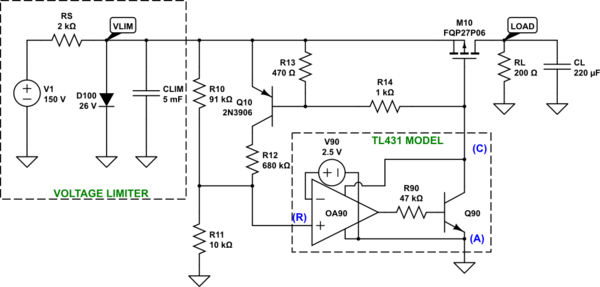
The 1st part of the circuit is the voltage limiter. The circuit you proposed has a fatal flaw: it will not work properly when the input voltage is exactly 24V - and that's the steady state of the overall circuit. When 150V via 2k is loaded with a 1.6W load, the voltage drops to 24V. Instead of an N-type pass element, we need a P-type pass element:

schematic

simulate this circuit – Schematic created using CircuitLab

This is the 2nd part of the circuit: the load switch with hysteresis. The load is turned on when the C1 voltage raises above 25V. The load is turned off when that voltage goes below 23V.

CLIM must be about 25x larger than the load capacitance CL.

schematic

simulate this circuit

\$\endgroup\$
9
  • \$\begingroup\$ I am not sure to understand when you said "When 150V via 2k is loaded with a 1.6W load, the voltage drops to 24V". The PNP Q1 and D1 acts as an LDO regulated at 30V. When the 1.6W is switched on it will pulls 53mA. C1 supply the inrush current. Since maximum current is 75mA it works and I have tested it and I confirm that C1 has to be increased (works with 4.7mF) \$\endgroup\$
    – hiak
    Commented Mar 3, 2023 at 8:13
  • \$\begingroup\$ Please turn D100 and change symbol to Zener. \$\endgroup\$
    – winny
    Commented Mar 3, 2023 at 9:27
  • 1
    \$\begingroup\$ @winny It’s an ideal simulation element. Turning it to a Zener would change behavior not to match what the previous stage is doing. \$\endgroup\$ Commented Mar 3, 2023 at 12:32
  • 1
    \$\begingroup\$ @hiak Try at lowest line voltage :) The 2k resistor is really marginal. It all just barely works. It makes the capacitor charge times long. It should have been 1k, and then the only reason for having it is to shed heat away from the pass element. \$\endgroup\$ Commented Mar 3, 2023 at 12:34
  • \$\begingroup\$ A breakover diode? \$\endgroup\$
    – winny
    Commented Mar 3, 2023 at 13:54
2
\$\begingroup\$

Without defining your entire circuit energy, power, voltage and thermal expectations you may learn something from your attempts, but this topology is unwise due to resonant condition with LC stored energy transfer without a controlled damping R.

I think that you would be far better off using a 2W offline AC/DC regulator topology such as the MP150.

https://www.monolithicpower.com/en/mp150.html

Edit1:

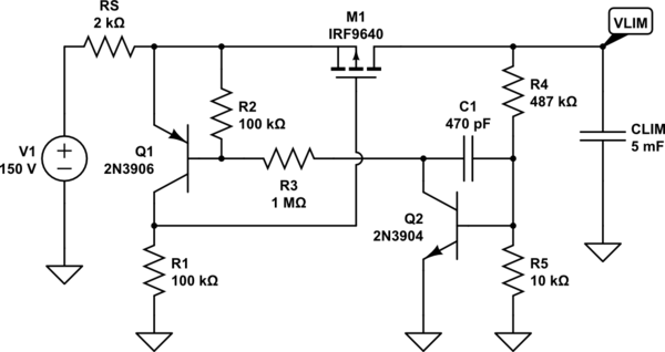
Ok back to your 1st option , replace the FET resistor with a comparator at sufficient threshold and add hysteresis. The input will sag due to input loading and you do not want it to oscillate on startup. Consider a 90% threshold and 20% hysteresis for a starting point.

enter image description here

You will have to monitor start using any switch at different Vin thresholds somehow to characterize performance to optimize these the parameters to ensure it will work. The Comparator and FET switch ought to be fast enough but will a few (?) milliseconds of storage time be enough to start it. Some time constants ought to be defined for each condition.

\$\endgroup\$
1
  • \$\begingroup\$ I have no access to the line the only available power is through the 2K power resistor. Otherwise it will be much easier \$\endgroup\$
    – hiak
    Commented Feb 27, 2023 at 18:51

Your Answer

By clicking “Post Your Answer”, you agree to our terms of service and acknowledge you have read our privacy policy.

Not the answer you're looking for? Browse other questions tagged or ask your own question.