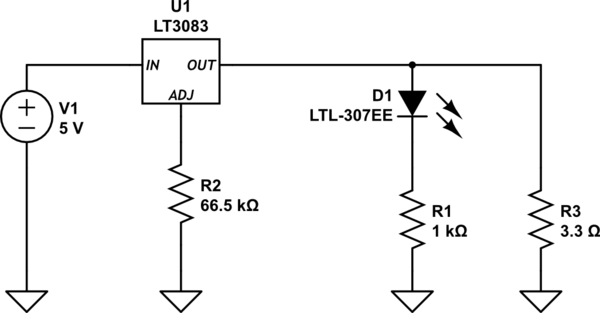
simulate this circuit – Schematic created using CircuitLab
I am trying to test my LT 3083 voltage regulator using a chip resistor to model the load. My input power was 5V and I was trying to create 3.3V using the LT3083 part. I added a green LED with a 1K ohm current limiting 0603 chip resistor. Then I put a 3.3 ohm chip resistor in parallel with the LED and the current limiting resistor without realizing the 3.3 ohm chip resistor was only rated for 0.25W. I was trying to put 1 ampere and 3.3V on the 3.3 ohm resistor which is 3.3W. Obviously, the resistor was failing but it seems the LED was also started to heat as well.
Initially, the LED started green and it started to become yellow before I removed power. I was still getting 3.3V on the net even though the resistor was failing. Once I replaced the 3.3 ohm, 0.25W chip resistor with 3,3 ohm, 50W resistor everything worked. My question is why was the LED burning out even with a 1k chip resistor when the parallel resistor was failing? It seems the LED path had a lot more current than planned when the parallel resistor was failing.
