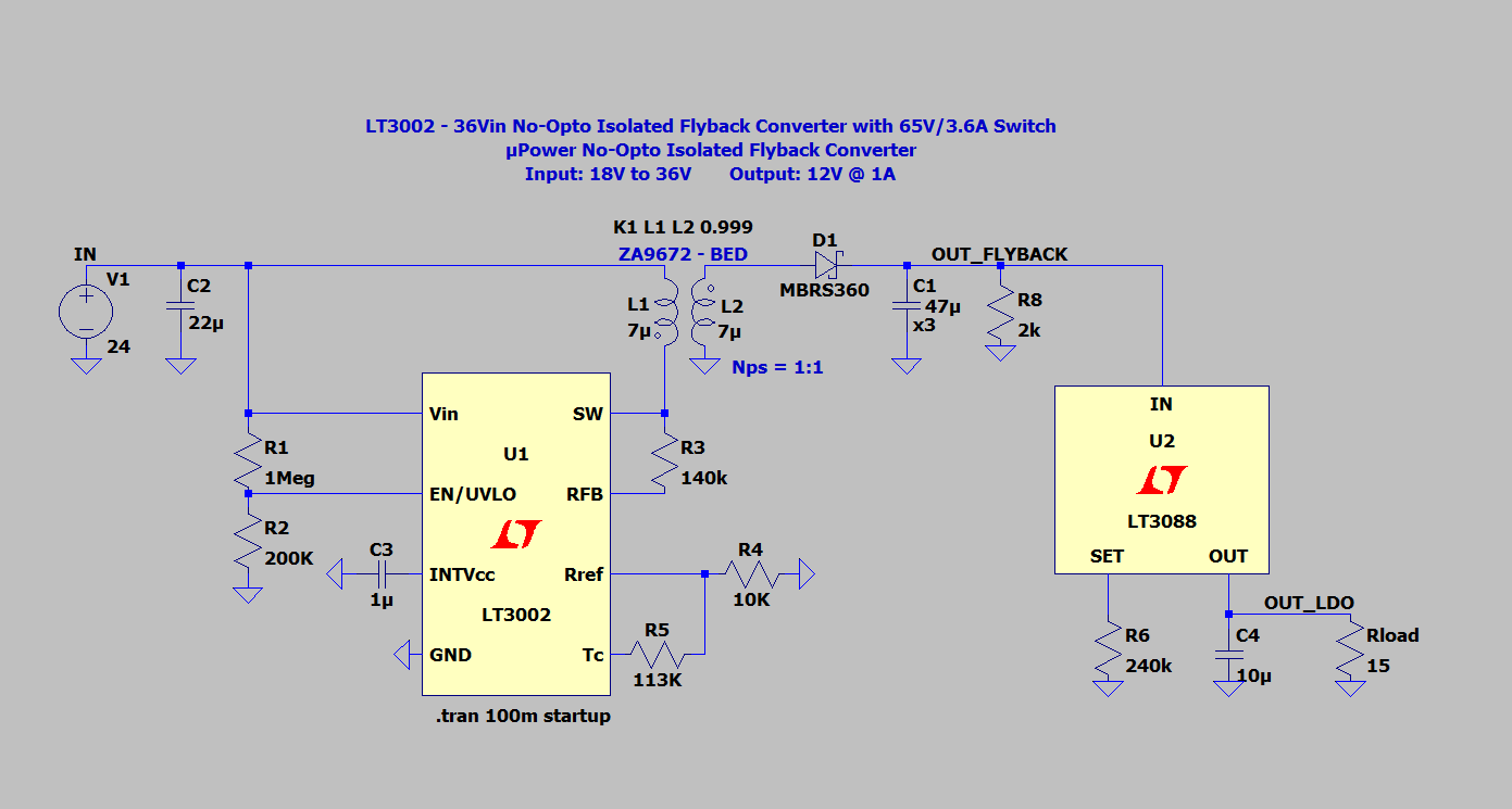
I am designing an isolated DC-DC converter
[snip]
want to use an LT3088 linear regulator at the transformer's output to get a stable 12V.
Any reason that you want to use a linear regulator on the output of the SMPS DC-DC converter?
Linear regulators are used typically on the outputs of a 230V 50Hz transformer with capacitor filter. In this case, the transformer won't provide a stable voltage since most transformers are lightweight and to create a lightweight transformer, you need lots of turns or else the core will saturate merely from the idle magnetizing current, meaning the resistance of the transformer windings is huge, meaning that any current at the output will create huge voltage drop. Also the capacitor filter creates pulsating DC, not true DC, meaning the linear regulator is needed.
This can be observed by an unregulated non-SMPS "DC" power supply that has a transformer and capacitor filter. Typically, a 12V nominal power supply can give you 16V or more when unloaded. The current rating is typically ridiculously low, let's say 0.5 amperes. When you put the 0.5 amperes, you will observe that the average voltage at the output isn't even the advertised 12 V, it's less than that! None of that happens in SMPS DC-DC converter power supplies.
However, SMPS DC-DC converters are typically a different beast. The frequency is very high, so a lightweight transformer will do without huge winding resistance. The ripple at the output is measured in millivolts. Because of the high frequency, the output capacitor can hold the voltage during a switching cycle, meaning no more capacitor ripple (unless you care about a millivolt ripple). No matter how much you load the output, it gives exactly the advertised voltage, until you hit the current limit, in which case it will start to reduce the voltage to maintain the current limit.
I guess someone might want to do an exceptionally low-ripple SMPS DC-DC converter. Typically you would want to do that by bumping up the frequency as high as possible and ensuring the capacitors are large enough, and ensuring the control algorithm is good. However, you might in addition further filter the output with a linear regulator to further reduce the ripple. This is made somewhat harder by the ripple rejection of linear regulators being optimized for mains frequency (50 Hz), and being much lower at typical SMPS operating frequencies. But it might reduce the ripple even lower, to allow using an SMPS in applications that absolutely demand the lowest possible ripple you can get.
This would be extraordinary, however. I don't believe any common lab power supply for example would use SMPS and linear regulators at the output of the SMPS.
Typically, SMPSes do not require linear regulators at the output.
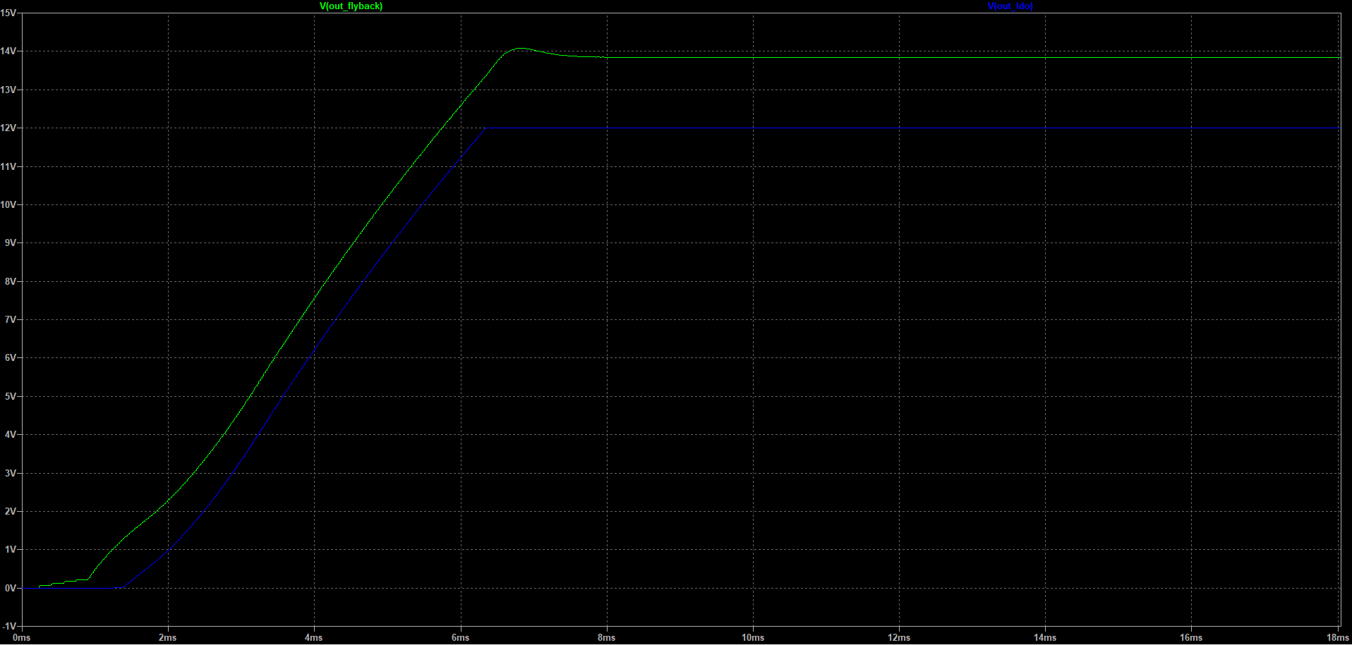
I am confused about if it can provide 14V (10W) or higher voltage on the ZA9672-BED (12V, 1A) rated 12V, 1A transformer. Will that cause any problems?
Transformers have no voltage rating, unless we are talking about isolation (and no transformer would have isolation rated only for 12 volts). Transformers have current rating and inductance. If the transformer is rated for 1 A, you can put 1 A through it. If they say it's rated for 12 volts (whatever that means) and you use it at 14 volts, you're fine. It will work. However, in some circuits bumping up the voltage from 12 volts to 14 volts might require slightly larger inductance for optimal operation. However, the increase from 12 volts to 14 volts is so small that it is extremely unlikely to cause any problems.
Furthermore, any general purpose SMPS IC allows setting an arbitrary voltage. The older answer explains how to set it with resistors.


