0
\$\begingroup\$

I have a cuckoo clock melody circuit that is connected to the 8 Ω 0.5 W speaker and I want to replace it with the 8 Ω 1 W speaker. When I connected it the output was not that much great as the 0.5 W speaker. What will change do I need to do?

Actually, I want a more brisk and strong sound from my cuckoo melody clock so replacing it with a bigger size and configuration speakers but it looks like the circuit output drive value is lacking to satisfy the required drive value for an 8 Ω 1 W speaker, i.e. (Drive Value) 5.657 VPP to 8 VPP.

Kindly suggest a modification for achieving the same.

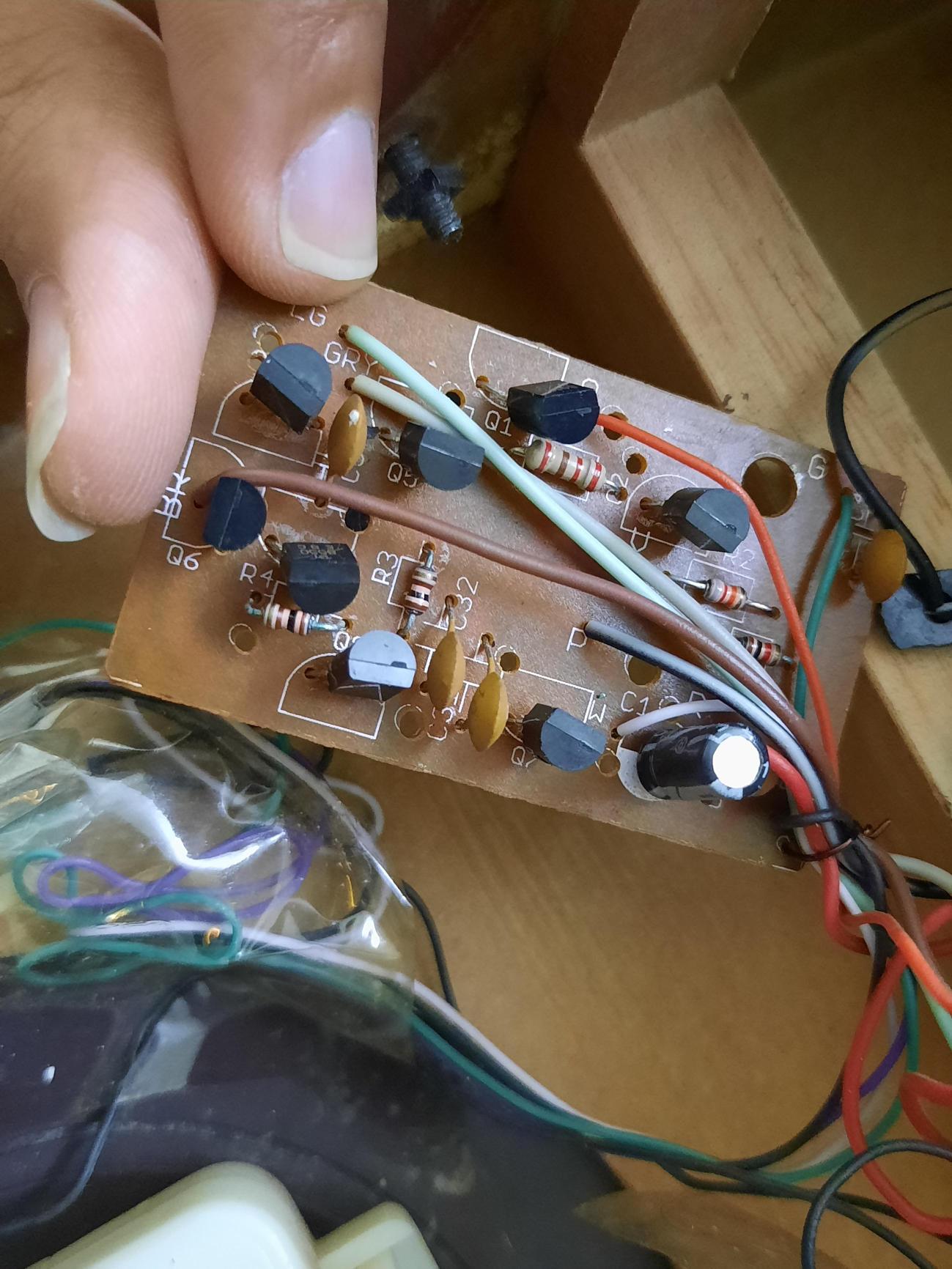
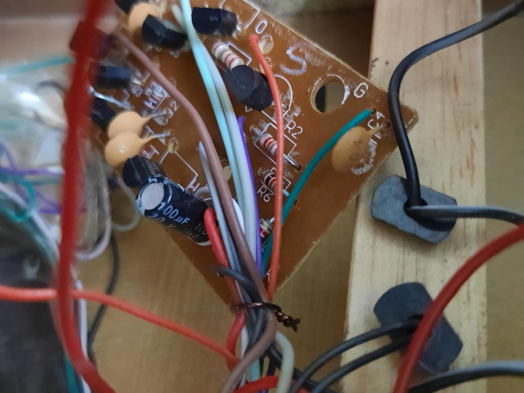
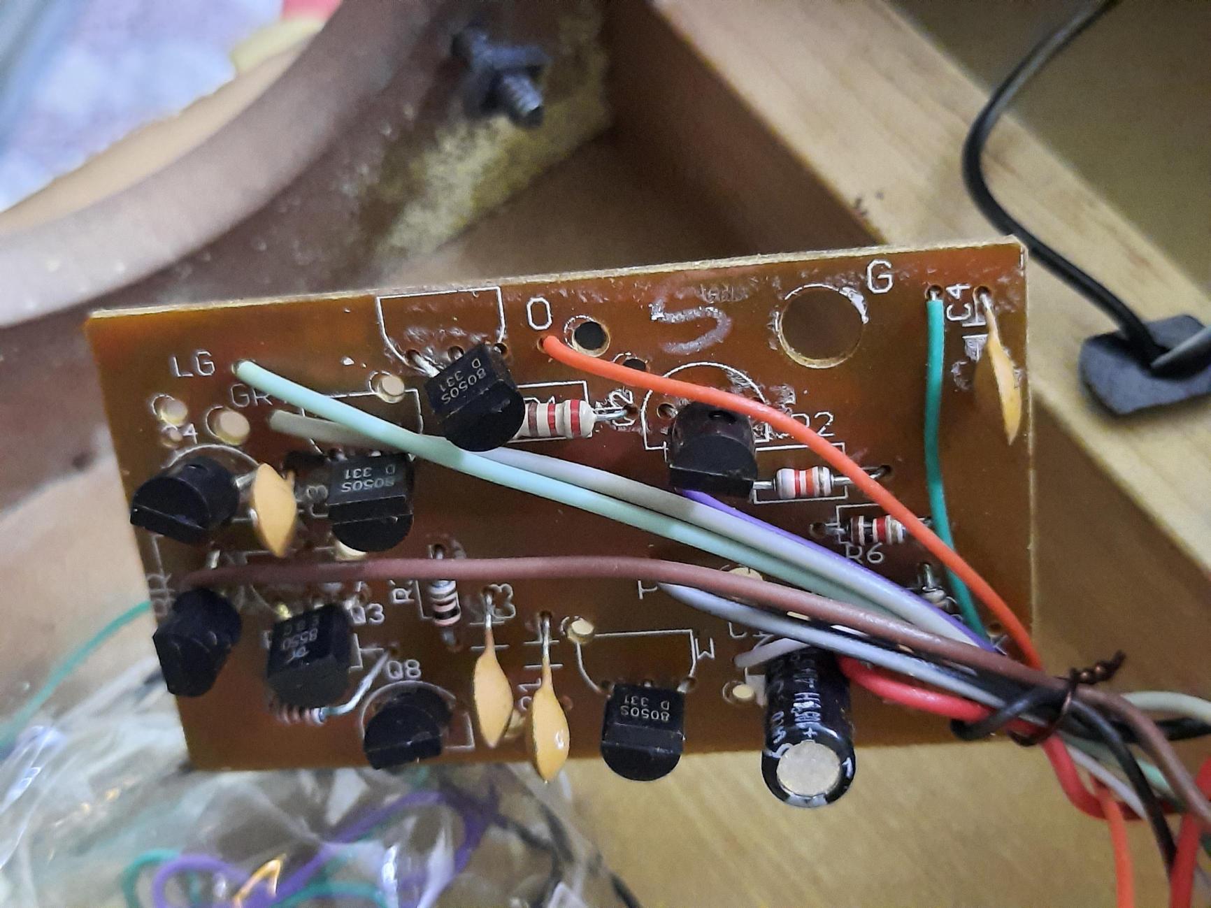
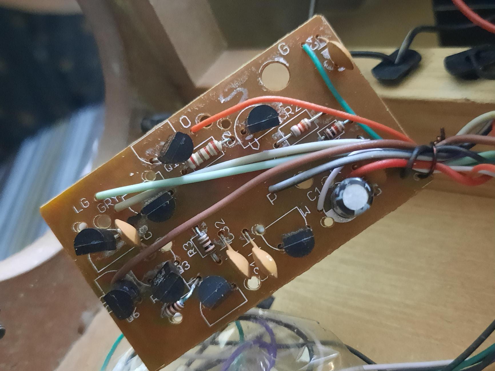
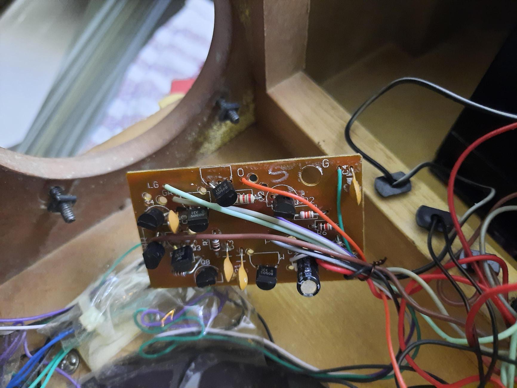
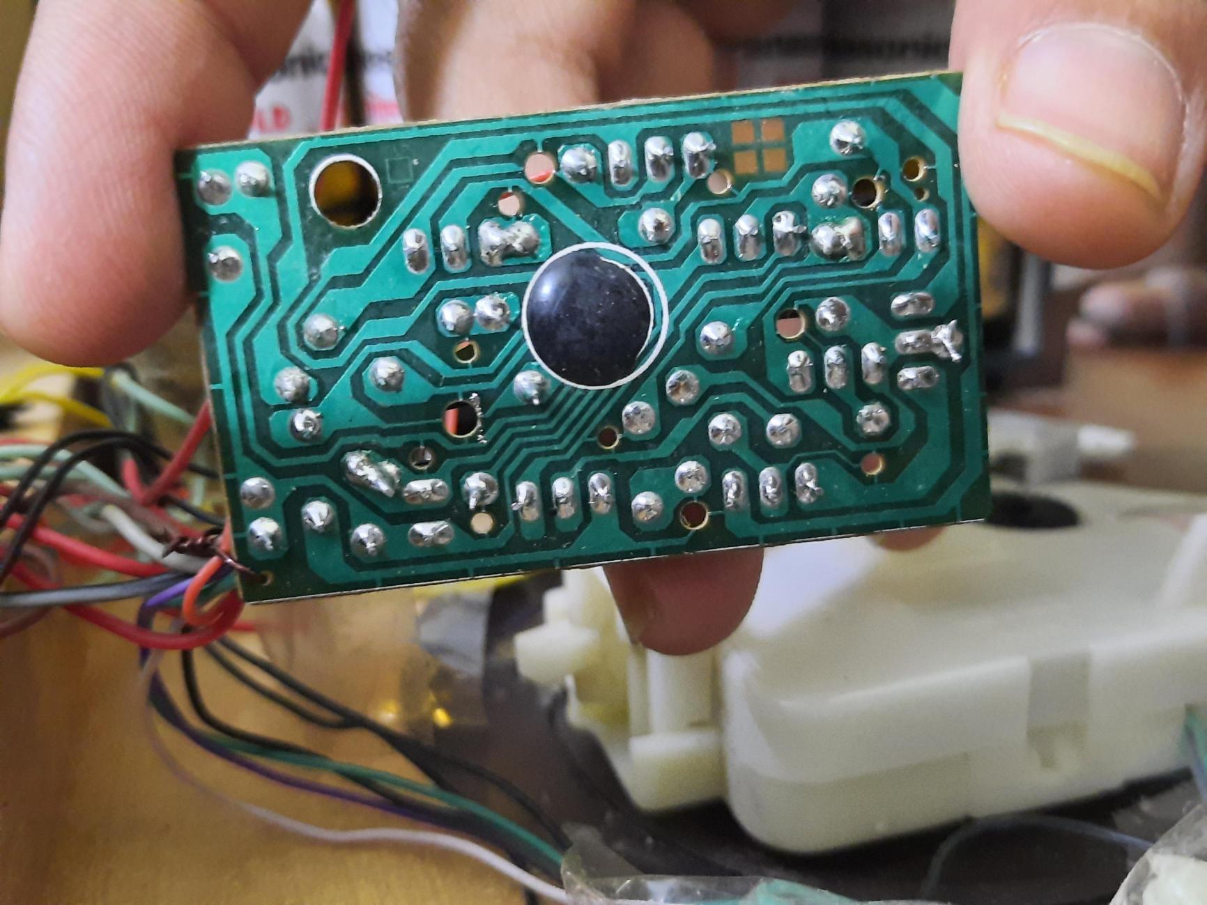
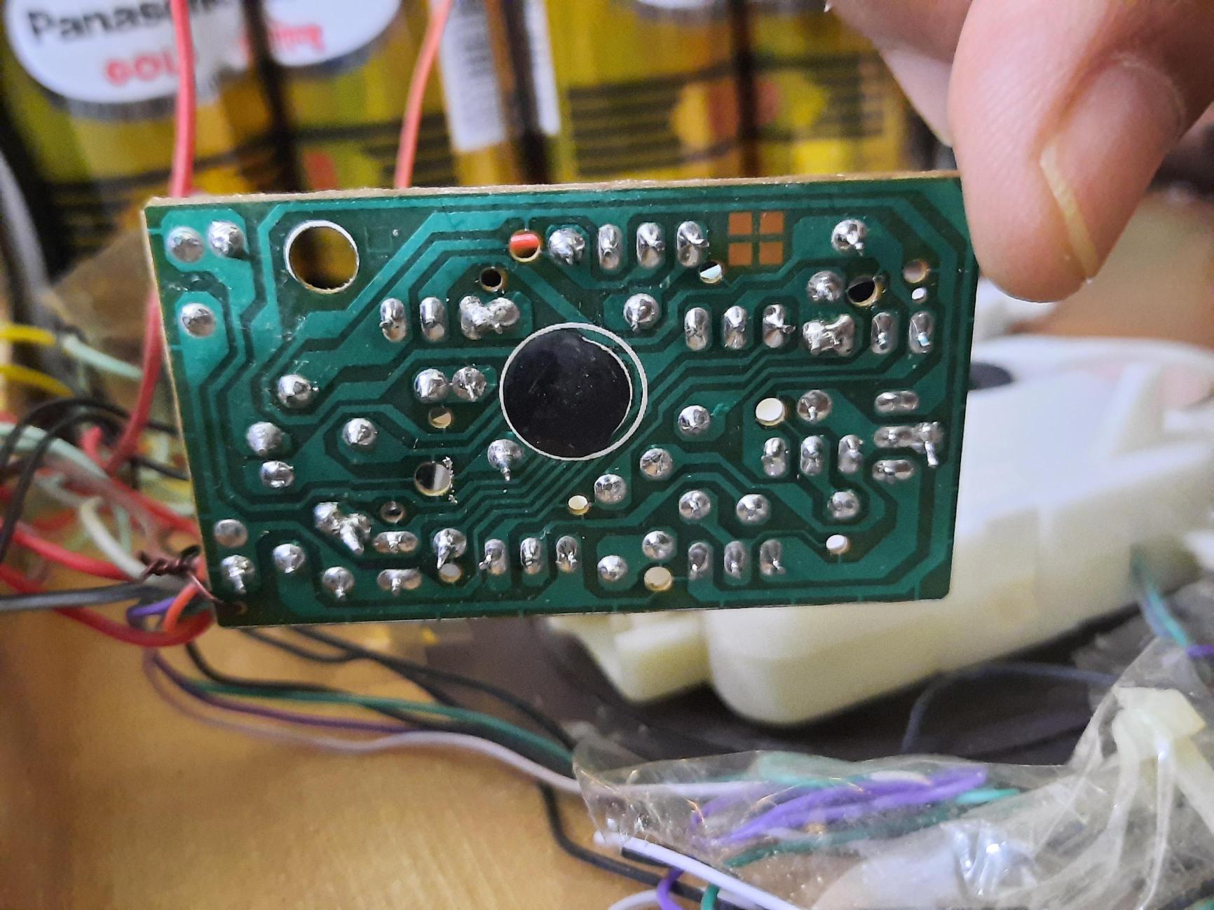
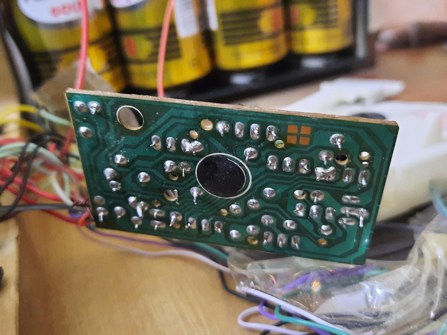
enter image description here enter image description here enter image description here enter image description here enter image description here enter image description here enter image description here enter image description here

Here the ORANGE wire is negative and red one is positive output to the speaker

\$\endgroup\$
5
  • \$\begingroup\$ You need an amplifier, but without knowing how the melody circuit drives the speaker I can't say how to connect it. Please show us a photo of the circuit board including where the speaker is connected and components around it. \$\endgroup\$ Commented Apr 12, 2023 at 5:50
  • \$\begingroup\$ Okay, will share in the evening. \$\endgroup\$ Commented Apr 12, 2023 at 6:05
  • \$\begingroup\$ What power source do you have available in the clock? If it only accommodates a small single cell battery then trying to get a 1w output may greatly reduce the battery life. The reverse engineering idea might be an easy first choice, some low cost designs might use a resistor in series with the speaker to purposely keep the output on the low side, if used shorting (or reducing the value) of such a resistor might give a boost to the output. \$\endgroup\$
    – Nedd
    Commented Apr 12, 2023 at 6:47
  • \$\begingroup\$ The clock is powered by 4 D-size cells. \$\endgroup\$ Commented Apr 12, 2023 at 7:55
  • \$\begingroup\$ Unfortunately your question was closed. While it seems you are not asking for repair advice but rather modifications, to continue you should make that fact very clear, (perhaps even alter the title). From here you could edit further, or start a new question with modification in the topic. Pictures of the PCB is a small start at understanding the circuit, though several of the same view are not so helpful. A reverse engineered schematic would be ideal. The PCB seems simple so this is one viable option. If you edit further or start a new question you can get my attention by using @Nedd. \$\endgroup\$
    – Nedd
    Commented Apr 22, 2023 at 8:01

1 Answer 1

1
\$\begingroup\$

That watt rating is not what the speaker requires or a measure of how loud it is;
it simply tells how much power the speaker can handle without burning up.

So of course two 8 Ω speakers will sound identical in volume if they are equally sensitive, i.e. can produce equal decibels at same power fed into them.

It won't change how much power the circuit can output to speakers.

What you can do is to put a 6 Ω or 4 Ω speaker to get more watts into the speaker, but it is unknown if the source can drive a heavier load.

Another option is to get an 8 Ω speaker with higher sensitivity, to get more decibels at same wattage.

A final solution could be to reverse engineer the circuit to figure out how to get more amplitude out of it, or how to add a separate amplifier if even possible.

\$\endgroup\$
2
  • \$\begingroup\$ I have bought the 8 Ω 1 W speaker, so wanted to do something with the circuit if possible to get desired output \$\endgroup\$ Commented Apr 12, 2023 at 5:53
  • \$\begingroup\$ @Nayan Panchal: To make things worse, in-use sensitivity depends on speaker enclosure (and room and placement with low frequencies). For frequencies of a melody clock, I'd look for a "closed chassis". \$\endgroup\$
    – greybeard
    Commented Apr 13, 2023 at 8:08

Not the answer you're looking for? Browse other questions tagged or ask your own question.