1
\$\begingroup\$

Screenshots:

enter image description here

enter image description here

imgur.com

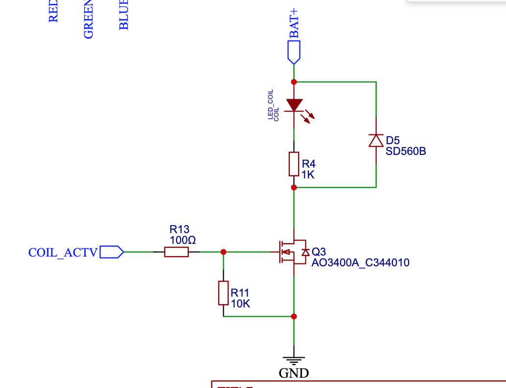
I need to apply up to 4.2 V to a 1.1-1.7 Ω coil. I want to apply this voltage only when COIL_ACTV is HIGH. COIL_ACTV is the output of a GPIO pin (3.3 V). To control this, I am using an AO3400A MOSFET.

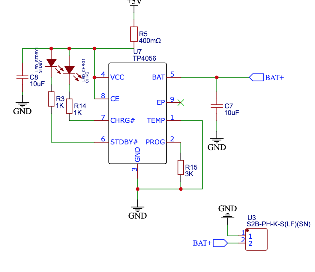
I have a battery charging IC (TP4056) connecting to my BAT+ as well. Should I disable battery charging when COIL_ACTV is HIGH? I’m worried that the output of the battery charger and the battery will combine and destroy the coil.

Am I running the risks of destroying any of my components? The coil will only be activated for seconds at a time. This device is being built into a vape.

\$\endgroup\$
2
  • 1
    \$\begingroup\$ When COIL_ACTV goes high, it just appears to turn on an LED, I don't see how that energizes your coil. Can you provide more of the schematic so we can see what you are trying to do? \$\endgroup\$ Commented May 3, 2023 at 20:42
  • \$\begingroup\$ @evildemonic In the final design, the coil will replace the LED_COIL and the R4 resistor \$\endgroup\$ Commented May 3, 2023 at 21:27

1 Answer 1

1
\$\begingroup\$

I think your circuit will work as drawn.

You have your charging chip set up to supply 400 mA current to BAT+, so this won't destroy your coil. Since the current is limited to 400 mA, and your coil resistance is low, the voltage here won't even go very high. The bulk of the current across the coil will be drawn from the battery.

Your choice of MOSFET looks good for this application.

It looks like you have a workable circuit here. The only question is if activating the coil triggers an error condition in the battery charger IC (unlikely, but if worried about it, toggle CE along with the MOSFET).

\$\endgroup\$
4
  • \$\begingroup\$ This would suffice right? imgur.com/a/sxdsjLc I just need to connect the CE pin to the node after the load? \$\endgroup\$ Commented May 5, 2023 at 2:28
  • \$\begingroup\$ @MichaelRutkowski Yes, you got it, well done. \$\endgroup\$ Commented May 5, 2023 at 14:18
  • 1
    \$\begingroup\$ Thank you for the help! When connecting to the CE pin from after the load, do I need a resistor to protect the IC? I found a schematic of the TP4056, i.sstatic.net/ZZY1E.png Does current go through the CE pin? Or does the CE pin just detect voltage? \$\endgroup\$ Commented May 5, 2023 at 14:50
  • \$\begingroup\$ It will draw a very very tiny amount of current. It may be good to include a small value resistor there for robustness (you have wisely added a diode to protect from the back EMF of the coil, but spikes may still be present.). 100 Ω would be my suggestion. \$\endgroup\$ Commented May 5, 2023 at 14:57

Your Answer

By clicking “Post Your Answer”, you agree to our terms of service and acknowledge you have read our privacy policy.

Not the answer you're looking for? Browse other questions tagged or ask your own question.