0
\$\begingroup\$

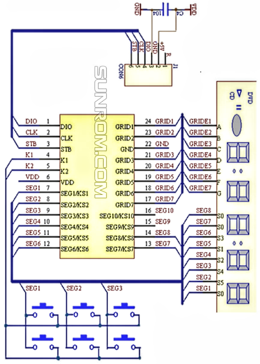
I have a robot mower that I'd like to make "smart" by using an Arduino compatible board to mimic key presses via the Blynk app. The control board of the mower is based on a [TM1668 chip] (https://www.sunrom.com/p/tm1668-soic24-led-displaykeypad-driver) (typical app circuit shown below)

enter image description here

and the 8 buttons are part of a 2x4 matrix I believe.

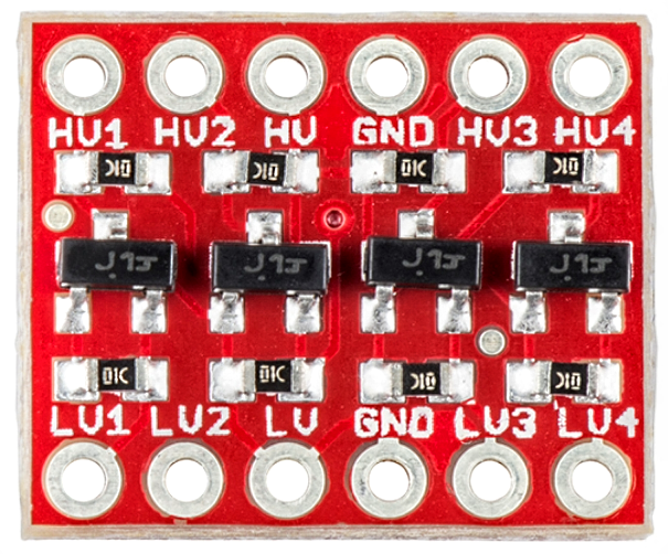
What's the best approach to mimic a key press with my microcontroller? I was thinking of using two BOB-12009 boards (SparkFun Logic Level Converter - Bi-Directional)

enter image description here

with each connected to one column pin and then the outputs connected to the row pins. This should solve the issue of mimicking a button press while the scan shifts across columns; please correct me if I am wrong.

I plan on using the same board also to "read" the state of the LEDs and feed that back into the Blynk app.

I did consider trying to use the Arduino to mimic the TM1668 board, but I would like the original control panel to continue working and I believe this solution wouldn't work with the behaviour of the strobe line, etc.

\$\endgroup\$
3
  • 2
    \$\begingroup\$ Please add a high level component view schematic of what you have and what you are trying to do. Otherwise, we will have no idea what you're talking about. A picture would also be worth its weight in gold. \$\endgroup\$ Commented Jun 21, 2023 at 2:32
  • 3
    \$\begingroup\$ CD4016 or CD4066 analog switches will do this. \$\endgroup\$
    – Jens
    Commented Jun 21, 2023 at 2:33
  • \$\begingroup\$ @Jens either that or a bunch of reeds will do it. Reeds maybe take more space but provide isolation and ESD protection. Industrial devices usually have keypads on dedicated connector. Reed board can be made as easily interchangeable option, fully compatible regardless of mower's schematic \$\endgroup\$
    – Maple
    Commented Jun 8 at 21:24

1 Answer 1

1
\$\begingroup\$

When reading or writing a matrix timing is critical if you get the timing wrong you'll see grid data in the wrong segment, or signal the wrong button press.

According to the data sheet the K1 and K2 lines are active high inputs with an external pull down (I can't read Chinese, but I can read schematics)

The K1, K2 lines are driven from the SEGx/KSx lines via switches. VDD is 5V but you mention level shifters, why? Arduino is 5V

Assuming you have some 3.3V microcontroller I would use TTL compatilbe CMOS "and" gates 74HCT08 followed by diode-or gates to drive the K1 K2 inputs.

If you have a 5V microcontroller the 74HCT08 will still be suitable.

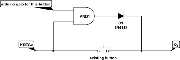
Basically 8 times this circuit:

schematic

simulate this circuit – Schematic created using CircuitLab If there's a diode in series with the existing switches don't have the diode between the and-gate and the TM1668

Another way to do it would be to program the Arduino to be an I2C slave (device) that is I2C compatible with the TM1668, but for this to work you may need to disconnect the existing TM1668. but this will probably not work if the host controller does not support full I2C (in particilar slave initiated waits) and will not work with the existing TM1668 connected unless the TM1688 language uses a 0 to indicate a press.

For reading the LEDs the easiest way is probably to tap into the I2C interface of the TM1668, assuming your microcontroller has a spare I2C interface that it can put into slave mode. else you'll be playing games with interrupts or polling trying to grab the grid data that is being sent at the right time. and you'll probably find that the grid outputs have an inconvenient voltage range (like 3.5V for high and 3V for low). pull-up resistors may be able to mitigate some of that

\$\endgroup\$

Your Answer

By clicking “Post Your Answer”, you agree to our terms of service and acknowledge you have read our privacy policy.

Not the answer you're looking for? Browse other questions tagged or ask your own question.