7
\$\begingroup\$

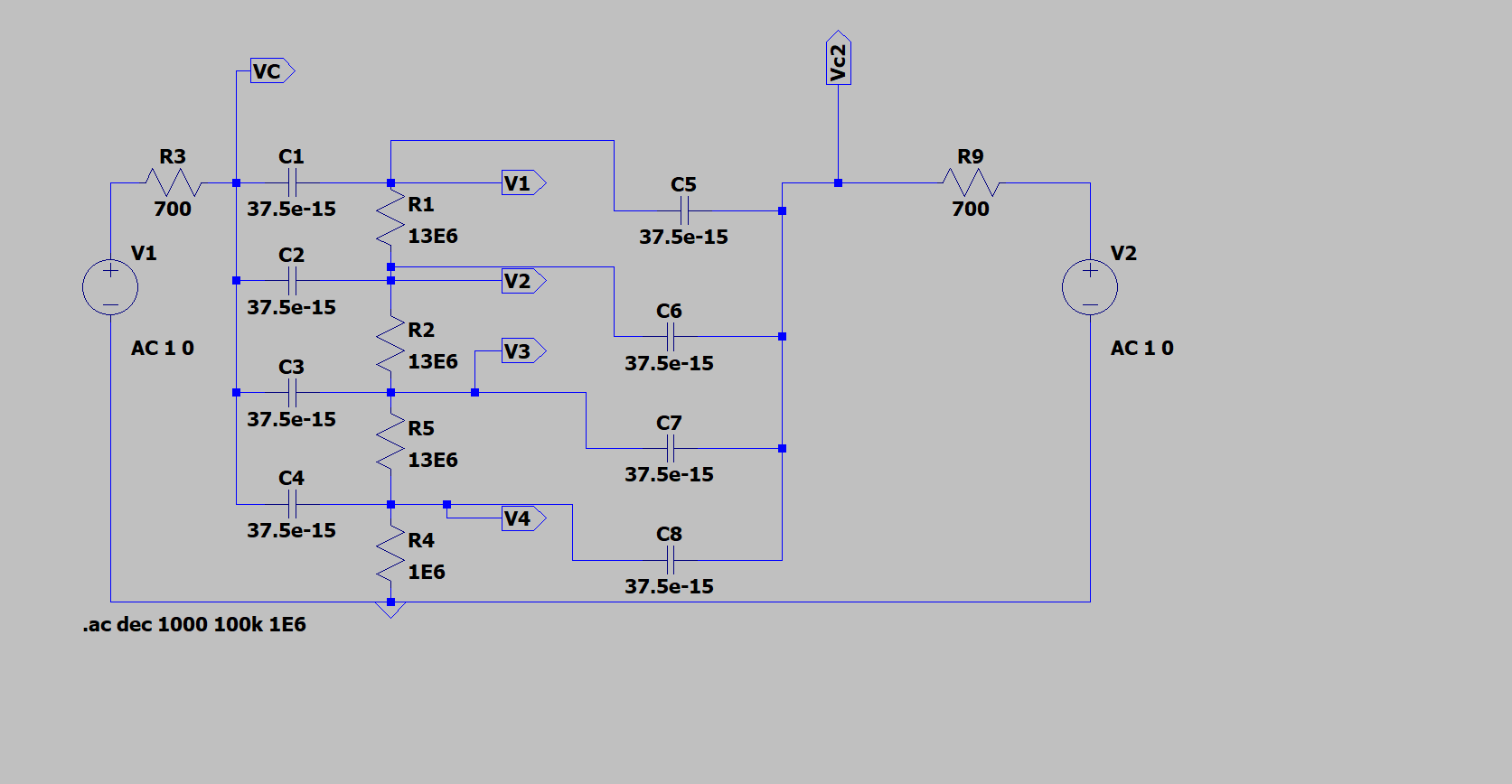
I was exploring a lumped approximation of a distributed RC network (sort of a lossy RC transmission line/ladder network).

Everything made complete sense until I observed the voltage "gain", and also the Kirchhoff law not being obeyed.

I probably make some stupid ignorant mistake, and here is the schematic:

I would expect the voltage on the RC ladder going in to cut-off at V1 first, then V2 and so on, ending with V4.

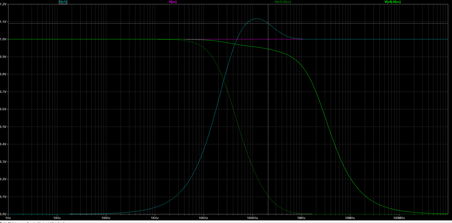
But when I run the simulation (decade AC sweep, 100 points per decade), this is what comes out:

Enter image description here

I have a problem with the voltage at V1 being bigger than 1 V. What is even more puzzling is the difference Vc - V1 (which would be the voltage over C1) is not zero when Vc = V1. Is it just because I have multiple sources?


EDIT:

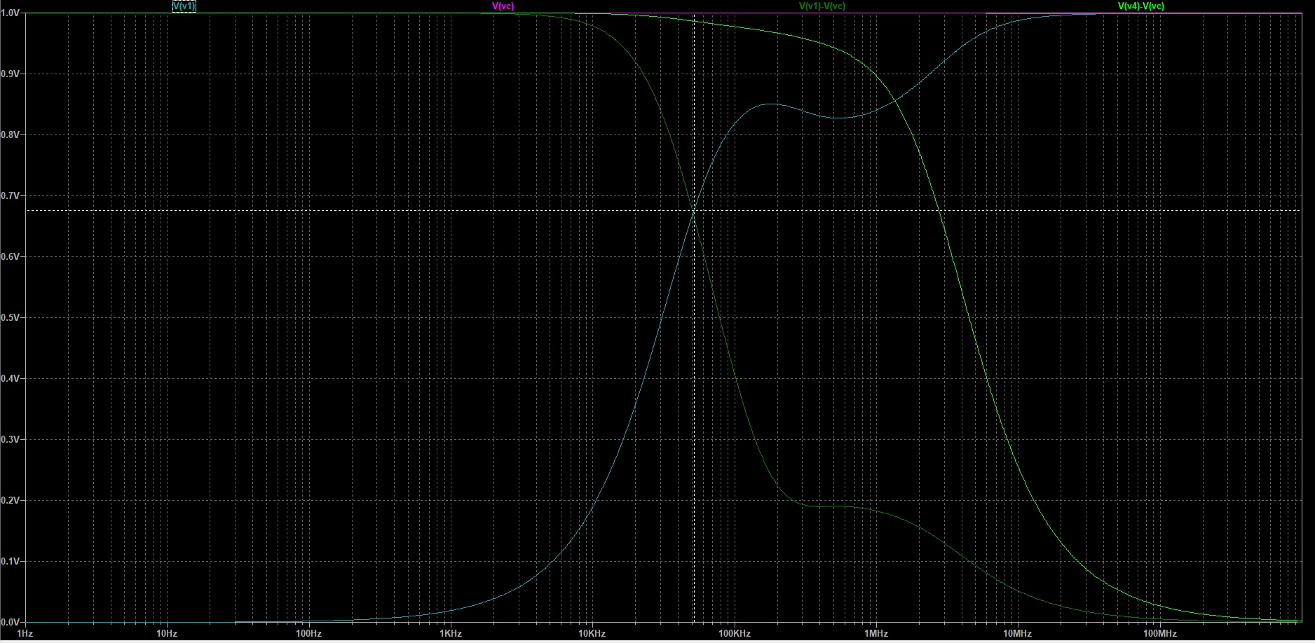
I removed the second source and the problem seems to be resolved. Should I conclude that using multiple sources like this is always a bad simulation setup?

Enter image description here

\$\endgroup\$
3
  • 2
    \$\begingroup\$ Effectively a duplicate of electronics.stackexchange.com/questions/242901/… , but considering it has poor answers, I think we can do better here. \$\endgroup\$ Commented Sep 27, 2023 at 18:50
  • \$\begingroup\$ thank you for the other link, did not find it before \$\endgroup\$ Commented Sep 27, 2023 at 18:55
  • 1
    \$\begingroup\$ If you have diodes, you can build voltage multiplier circuits out of diodes and capacitors. As the AC driving voltage swings one way, a capacitor gets charged. The diode keeps it from discharging and so as the AC swings the other way, its voltage rides on top. So there is a kind of memory effect, right? Capacitors have memory on their own; due to the phase shift caused by the lagging discharge, we can have moments when the capacitor charge rides the crest of the driving voltage, so to speak. \$\endgroup\$
    – Kaz
    Commented Sep 28, 2023 at 7:02

3 Answers 3

19
\$\begingroup\$

Aha, you've discovered the (in)famous(?) RC network with gain!

You may find this of interest:
Synthesis of Passive RC Networks with Gains Greater than Unity, Epstein, Proc. IRE, vol. 39, no. 7, pp. 833-835, July 1951

Basically, the phase shift of each successive stage can add just a tiny bit onto the previous, in such a way that real voltage gain is had -- albeit at extraordinarily low current (high impedance) for any meaningful ratio. A geometric series (of RC values) optimizes gain, if you're curious.

\$\endgroup\$
3
  • \$\begingroup\$ interesting, thank you. I still do not understand why the curve of the expression (V(v1)-V(vc)) does not match the curve of V(v1) minus the curve of V(vc) \$\endgroup\$ Commented Sep 27, 2023 at 19:10
  • 3
    \$\begingroup\$ Phase. |a + b| does not equal |a| + |b| in general, and is only true when a and b are in phase. \$\endgroup\$ Commented Sep 27, 2023 at 19:48
  • 1
    \$\begingroup\$ a yes of course, its adding the phasors, silly me. Thank you very much for your help \$\endgroup\$ Commented Sep 27, 2023 at 19:50
2
\$\begingroup\$

If you are using super capacitors and superconducting wire (like you are in the simulation) then yes, it does seem kind of weird. But if you could build a system such as this then I would expect it to be correct.

I would do a transient simulation, and watch how the capacitors charge at that frequency where the hill is.

The last thing would be to put in actual parasitics, put in some inductance for wire (most traces on a PCB add ~10 nH per inch). Capacitors will also have a few nH of ESL and some ESR depending on the type. You can select an equivalent if you right-click on the capacitor.

\$\endgroup\$
1
\$\begingroup\$

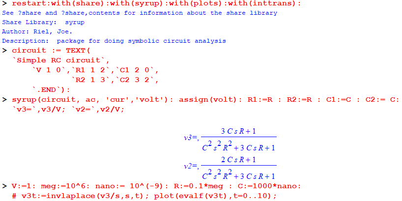
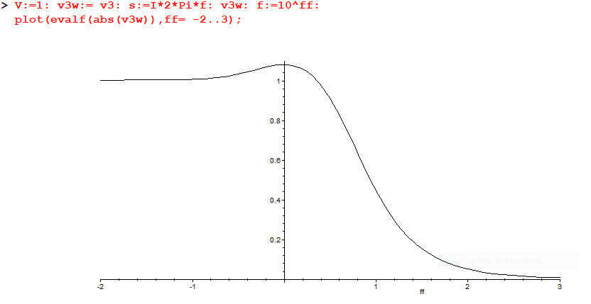
Here is a Maple sheet to calculate output ...

enter image description here enter image description here

ff is log(f).

\$\endgroup\$

Your Answer

By clicking “Post Your Answer”, you agree to our terms of service and acknowledge you have read our privacy policy.

Not the answer you're looking for? Browse other questions tagged or ask your own question.