2
\$\begingroup\$

This is one of those problems that seemed super simple at first but, after simulating, appears to be tricker than I expected, at least for my wannabe-EE brain.

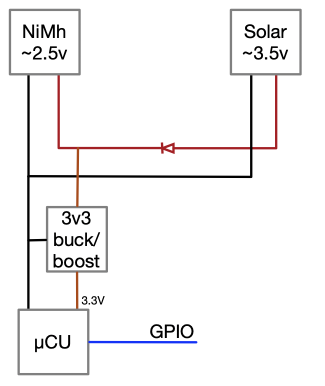
The circuit I'm working with looks something like this:

circuit diagram

As you can see, we have a very simple solar-powered microcontroller with a battery backup. A buck/boost converter generates the 3.3V needed for the microcontroller. This circuit works pretty well, but on particularly sunny days we can overcharge the battery.

To address this, I wanted to add a way for the microcontroller to disconnect the solar panel. In order for this to work, the mechanism would need the following requirements:

  1. Low impedance when "on", so that we don't waste energy.
  2. Needs to default to "on" if the microcontroller GPIO is high-z (to allow for cold-starts when the battery is depleted)

That's it. I don't care if it is a high or low signal from the microcontroller, or what side of the solar connection gets interrupted. As long as it is low impedance when on. Seemed so simple.

At first I thought I could just use a MOSFET to interrupt the low or high side of the circuit, but I immediately ran into problems getting the MOSFET to always turn completely on or completely off in the simulations.

One of the tricky problems is that the voltage from the solar panel is variable: it can be anywhere between 2.5V and 3.5V when under load, or as high as 6V when unloaded (like when turned off). The microcontroller GPIO can only source 3.3v, which might be higher or significantly lower than the solar panel voltage.

I could use a bipolar transistor, but I'd rather avoid the voltage drop. At these scales, every 10th of a volt counts.

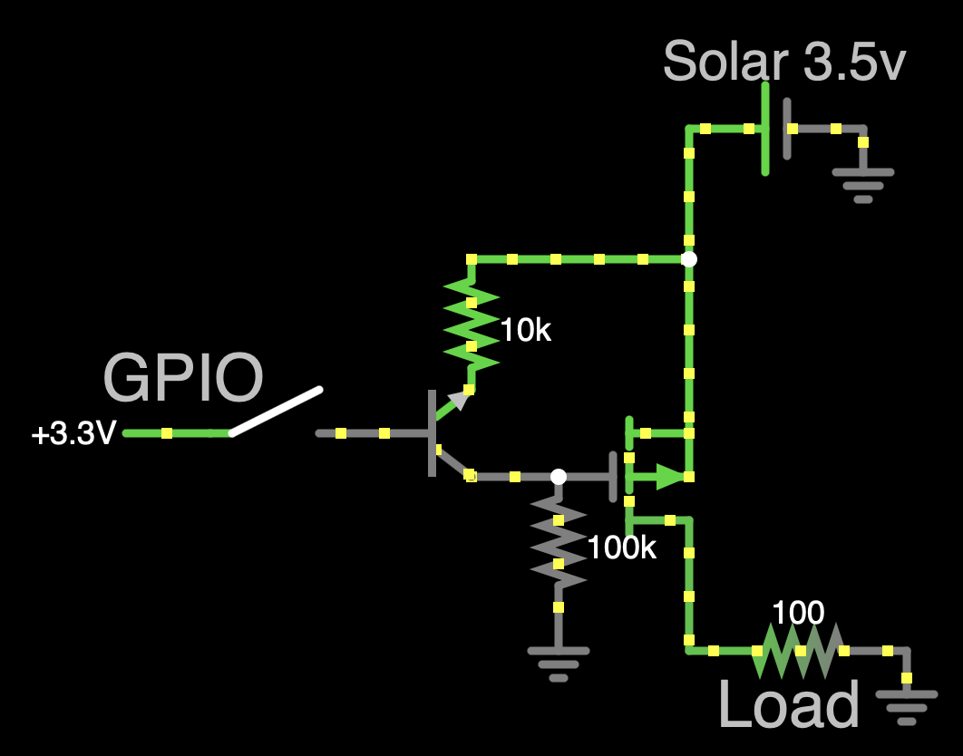
This was the closest solution I could come up with:

Bad Circuit (Simulator Link)

At first this seemed like it was working well enough. It defaulted to being on, but problems arise when the voltage of the solar panel increases. For example, in the case above only 2.6V is making it to the load, which way too large of a voltage drop.

I'm sure there is some easy way to do this that I'm just not seeing. I could use a small relay, but those are expensive. It seems like there must be a better way using solid-state electronics.

If I find a good enough mechanism, then perhaps it might even make sense to use it instead of the diode... But I digress.

\$\endgroup\$
4
  • \$\begingroup\$ The BJT looks like it is either the wrong polarity, or wired backwards. It might still work, but the current gain will be low. \$\endgroup\$ Commented Sep 30, 2023 at 20:45
  • \$\begingroup\$ Yes, but swapping it around doesn't appear to make any difference in the circuit. \$\endgroup\$ Commented Sep 30, 2023 at 20:51
  • \$\begingroup\$ You MUST say what type the MOSFET is. What type the BJT is is less important. \$\endgroup\$
    – Russell McMahon
    Commented Oct 1, 2023 at 10:56
  • 1
    \$\begingroup\$ Kevin's answer is good. Short circuiting a PV panel does not hurt it. || As shown the FET gate MUST be at least Vgsth below it's source . If you see 2.6V out for 3.5V in the FET is getting 3.5-2.6 = 0.9 V Vgs to turn it on. That's quite a good FET - its just not being used well. \$\endgroup\$
    – Russell McMahon
    Commented Oct 1, 2023 at 11:06

2 Answers 2

4
\$\begingroup\$

For terminating the charging from a low power solar panel an easier approach is to short it out with a transistor driven from the GPIO.

Connect the bypass transistor directly to the panel before the isolation diode. When activated the voltage of the panel will go to a very low level so the diode will be reverse biased and charging will be stopped.

Solar panels can tolerate being short-circuited with no bad effects.

You don't say what short circuit current the panel can provide. Up to a few hundred milliamps I would use a small BJT. For higher currents a MOSFET would be appropriate.

\$\endgroup\$
2
  • \$\begingroup\$ If using a MOSFET, be sure to check that it's adequately turned on at 3.3 V on the gate; that's too low to turn on a standard power MOSFET, but special-purpose "logic-level" FETs exist that work at 5 V or 3.3 V. \$\endgroup\$
    – Hearth
    Commented Sep 30, 2023 at 23:52
  • \$\begingroup\$ Of course! Why didn't I think of this? Thanks for the idea! \$\endgroup\$ Commented Oct 1, 2023 at 18:13
1
\$\begingroup\$

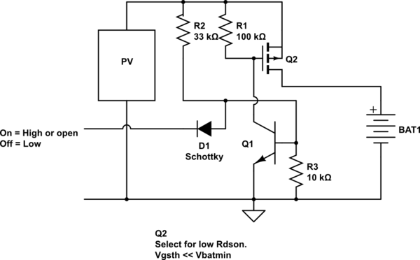
This should work.

PV panel >= Vcharge min.
Vcontrol floating or 3V3.
Vq1b about 1/4 VpV = Q1 on.
Q2 on due to Q1 gate pulldown.
Ensure Q2

  • Vgsth << Vbat_min (so FET always on when VPV higher than Vbatmin.
  • Rdson low enough for Icchgmax Adjust R2, R3 to suit for lower VPV.

Vcontrol ~= 0V. Q1 off. Q2 off
D1 Schottky so pulled down Q1 base < Vbe_turnon.

schematic

simulate this circuit – Schematic created using CircuitLab

Not tested or simulated. E&OE.

\$\endgroup\$

Your Answer

By clicking “Post Your Answer”, you agree to our terms of service and acknowledge you have read our privacy policy.

Not the answer you're looking for? Browse other questions tagged or ask your own question.