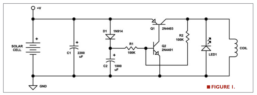
This circuit is designed to work with a low-voltage solar cell. If you aren't using a solar cell, you need to simulate its characteristics. It must have a large equivalent source resistance, large enough so that when Q2/Q1 latches, C1 will mostly discharge.
Edit: Jens comment caused me to think about the some more, and I now believe that the LED direction in the question is correct. When the magnet approaches the coil, the current generated will light the LED. When the magnet departs the coil, the current generated will trigger Q2/Q1. When Q1 is ON, the current will cause the coil to repel the magnet. (end edit)
Q2 must be nearly off at the start. If it isn't increase R2 until it is.
The cycle is started when the magnet passes near the coil and a voltage is generated at the coil. This turns on Q2, which turns on Q1. They will remain on until the voltage on C1 decreases far enough so Q2 isn't on anymore. Then the Q2/Q1 latch releases, C1 charges up, and the circuit waits for the magnet to pass by the coil again.
There is probably a better way to simulate the magnet passing near the coil, this is the best I could quickly create.
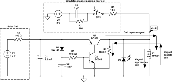
simulate this circuit – Schematic created using CircuitLab
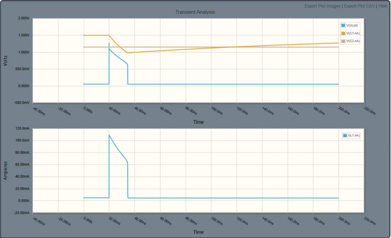
Edit2:
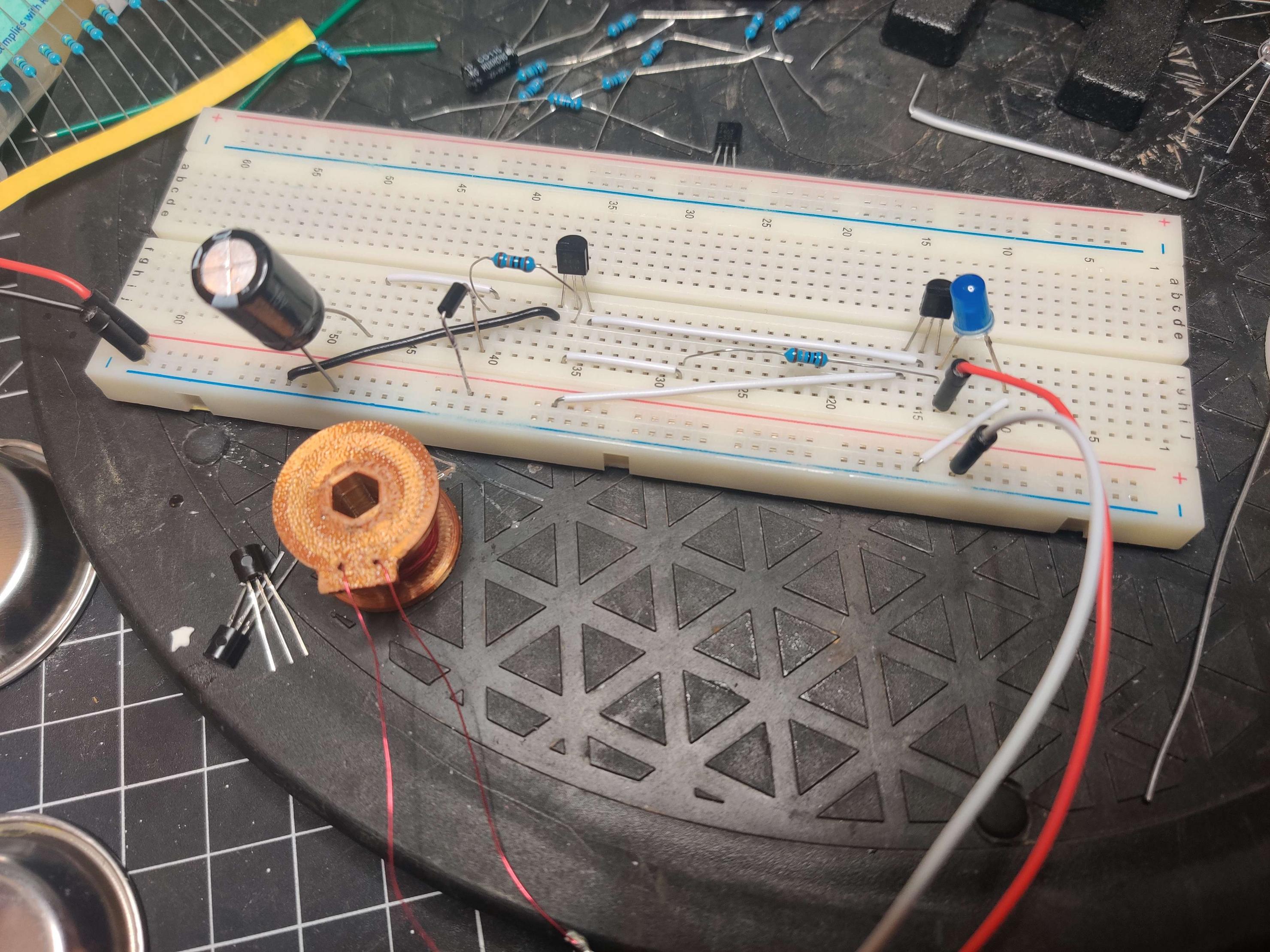
I built the circuit. As I expected, these minimalist circuits can be fussy. I did get it to work, but it is very sensitive to the supply voltage. And, it sometimes has high-frequency electrical oscillations. The oscillations could probably be solved with a PWB (I used a solderless breadboard).
There are several webpages that discuss this circuit, but they all miss the educational opportunity, none of them describe how magnets interact with coils.
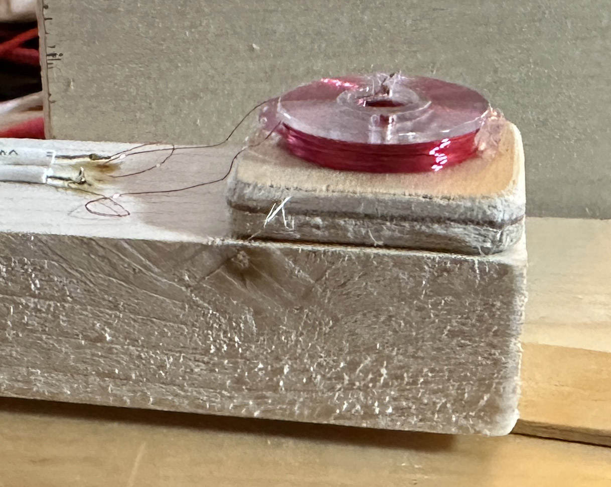
The coil is 34 AWG wire wound on a Class 15 plastic sewing bobbin. I wound it until it was almost full. I used a drill and a 1/4 inch bolt to wind it. The resistance is about 45 ohms. The average diameter is about 0.5 in, so there are about 1300 turns.
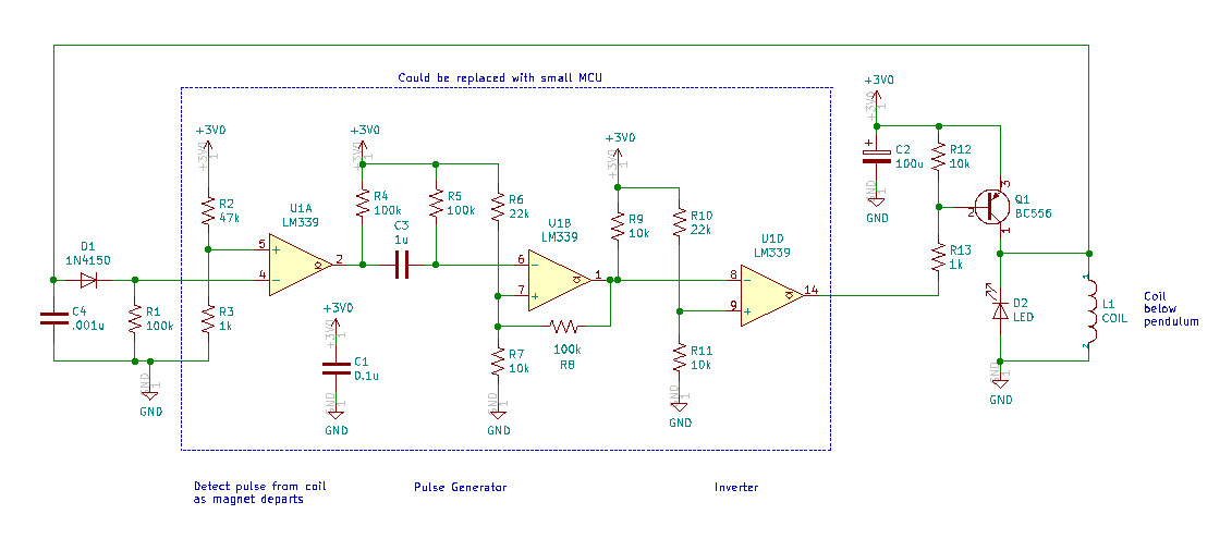
I designed and built and alternative design that is more robust. I designed it for 2 AA batteries, although it works with a supply voltage of 1.8 V to 10 V. Note that below 2 V the LM339 isn't guaranteed to work. And below about 2.3 V, the common mode input range of the LM339 is being violated.
The LED serves as a flyback diode. If you don't need a light, substitute a standard diode. You should have something to limit the negative pulse or you may blow out the transistor.
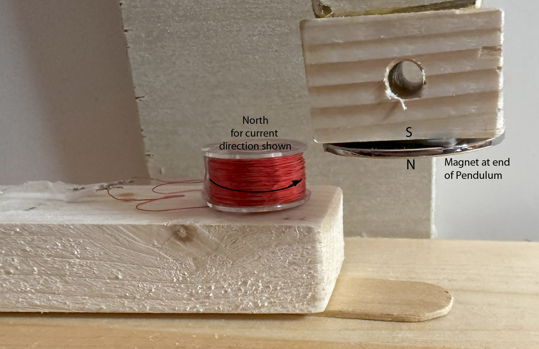
The magnet must be a strong rare earth magnet. The one I used is a little over 1 inch in diameter. The spacing between the coil and magnet must be small, aim for 1/16 of an inch.
The magnet and coil polarities must be setup to repel. The North/South on the magnet won't normally be marked, but if you can determine the magnet polarity, then put the North side down and orient the coil current as shown in the figure. Or, use trial and error. Put one volt on the coil and see if it repels the magnet on the pendulum, if not reverse the leads.
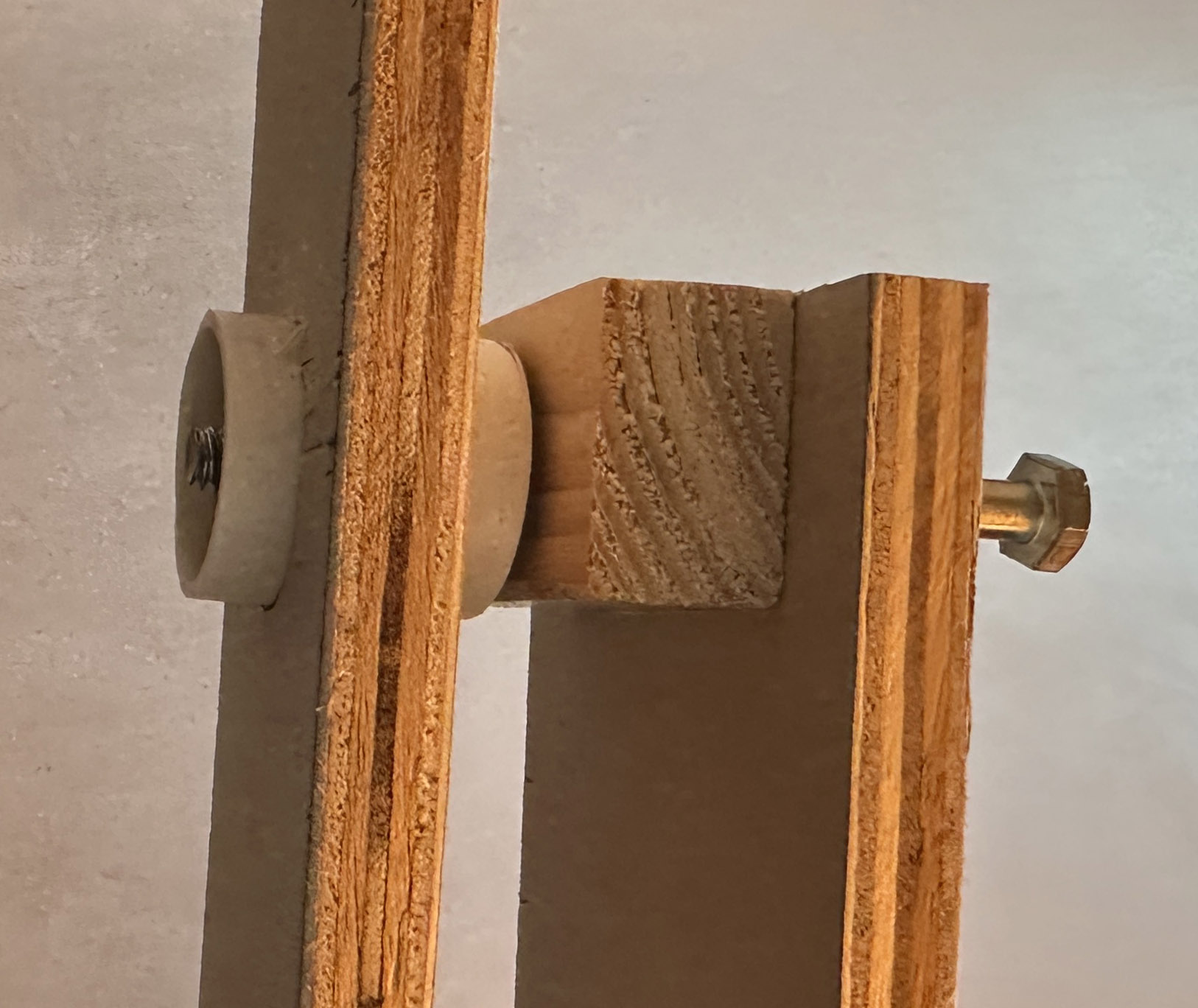
The pendulum is built from scrap wood. The nail pivot has a lot of friction, a lower friction pivot would be better. Be sure to keep any ferromagnetic materials a few inches away from the magnet. That is a brass screw in the picture.
The coil pulse time could be optimized via experiments. 40 mS is probably too long. The magnetic force falls off rapidly with distance.
At 3 volts, the quiescent current is 1.3 mA, the average pulse current is 3.1 mA, a total of 4.4 mA. If you are using AA batteries to power a clock pendulum, you want to get the total current below 0.2 mA (assuming one year battery life). You need a lower friction pivot point, bigger coil, shorter pulse, and lower quiescent current.
Note that a modern solution would be to use an MCU. I would use an MSP430G2553 because it is ultra-low power and I am familiar with it. There are many other MCUs out there. It does need to have an integrated ADC, the input on the left is a small analog voltage.
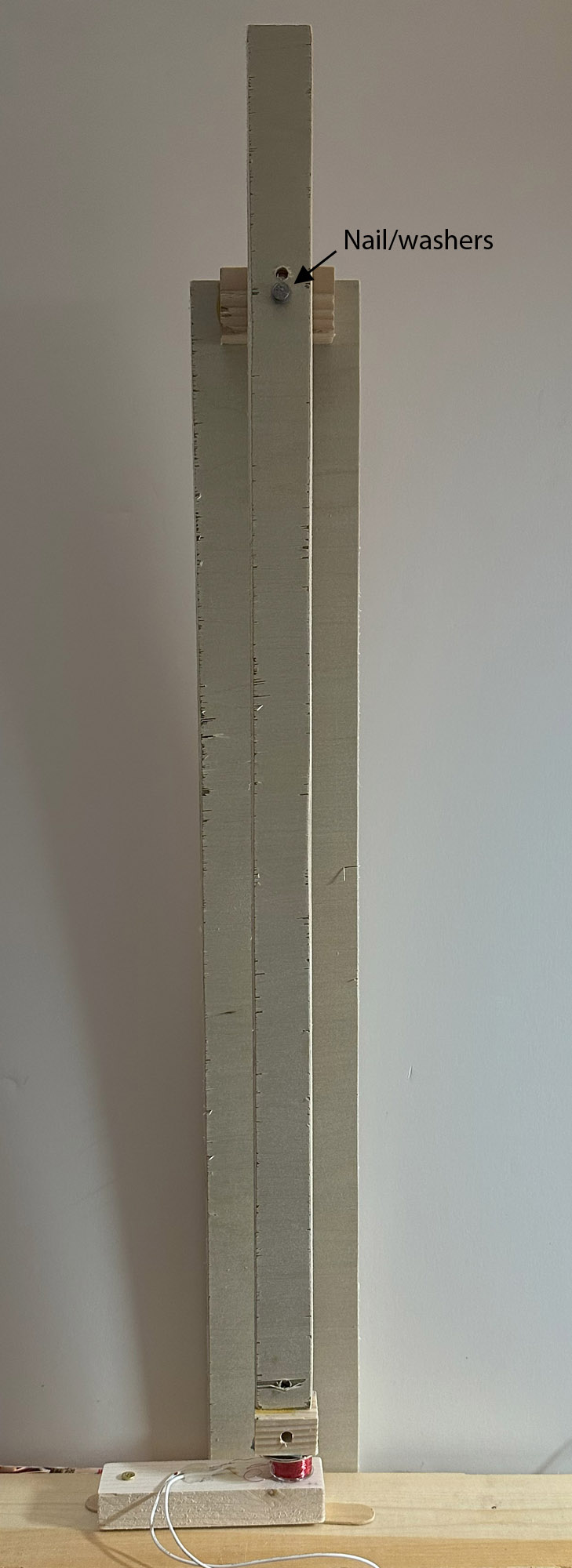
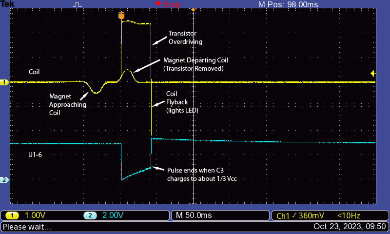
Edit3: Improved the design with a flatter coil, you want the wires in the coil to be as close to the magnet as possible. To do this, I modified the bobbin so it is less thick. Used 38 AWG this time. Resistance is now 97 ohms.
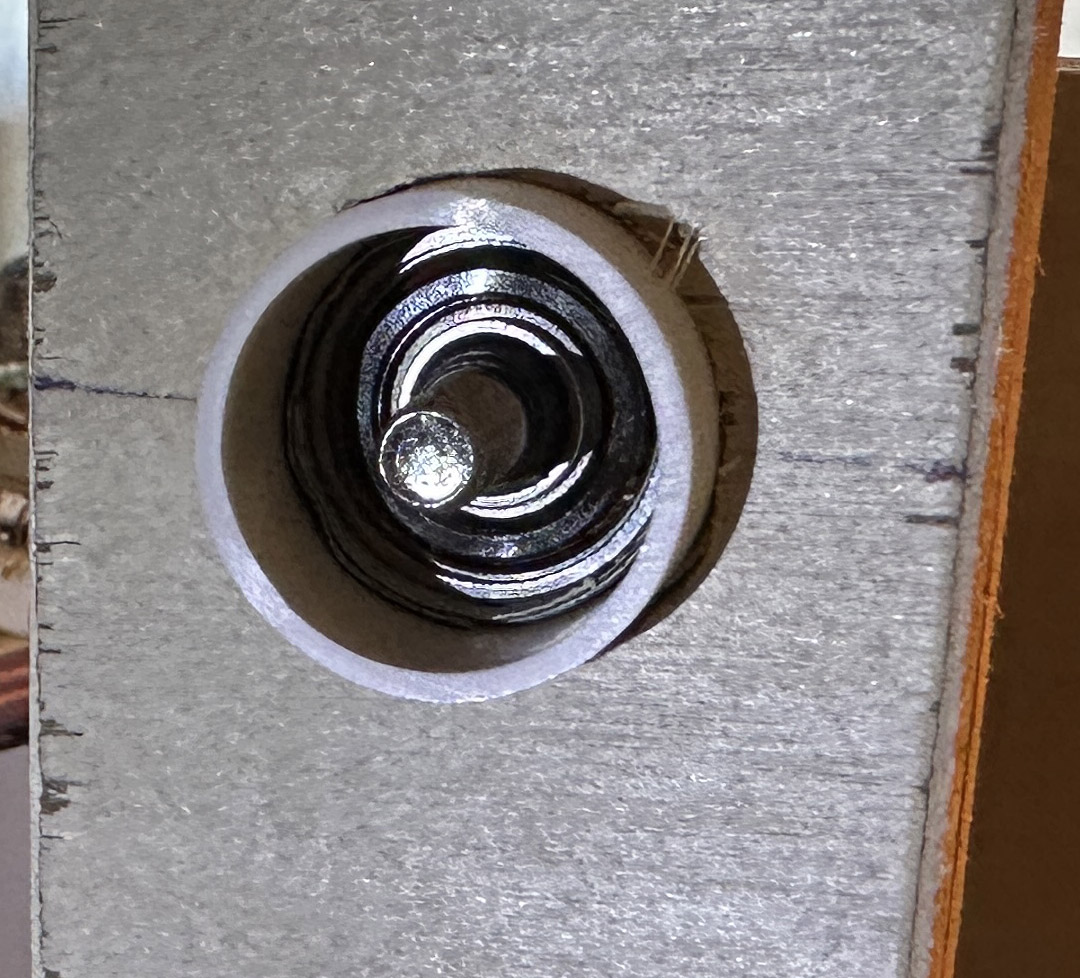
Changed to a ball-bearing fidget spinner bearing. The PVC pipe interface is to keep small wood particles out of the bearing. This improvement wasn't as much as expected, I estimate only about 1/3 the friction of a nail in wood.
Shortened the pulse width to about 8 mS. C3 = 0.2 uF.
Assuming that the driver electronics is changed to an MCU, the circuit will now last close to a year with 2 AA batteries.
