0
\$\begingroup\$

I conjecture that any \$RLC\$ circuit with \$n \ge 0\$ independent sinusoidal voltage sources of the same frequency is exponentially stable.

How to prove this or if this is not true, how to modify the condition and prove the corresponding result?

I find the general characteristic polynomial's roots not so easy to analyze to show that all of them have negative real parts.
Having an answer to this question would surely help, but I'd like to see any other approach, desirably as many other rigorous approaches as possible.

I tried to form a general system of ODEs using voltage node method as follows:

Say we have a reference node \$0\$ and nodes \$v_1, ... v_n\$. Consider an arbitrary node \$v_k\$. The equation for it will go into \$k\$-th row of the system matrix.

Define the following functions used to represent the currents:

$$f_R(R, v) = \frac{v}{R}$$ $$f_c(C, v) = C\frac{dv}{dt}$$ $$f_L(L, v) = \frac{1}{L}\int v dt$$ $$f_0(0, v) = 0$$

Then, using KCL, the \$k\$-th row will be:

$$-f_{\text{component_type}_1}(\text{component_type}_1, v1), \ ... \sum_{\text{component_type_i}} f(\text{component_type_i}, v_k), \ ...-f_{\text{component_type}_n}(\text{component_type}_n, vn), \ \sum_{i = 0}^m x_i$$,

where component types \$\in \{R, L, C, 0\}\$ depending on which component is directly connected between nodes \$v_i\$ and \$v_k\$ and \$x_i\$ are the sinusoidal sources connected directly to \$v_k\$.

The main difficulty in analyzing such a system is its generality. In order to eliminate the integral in \$f_L\$ functions I would have to differentiate the equation, but since I don't know whether the inductor is present or not, I have to differentiate all the equations, which further complicates the analysis.

\$\endgroup\$
10
  • \$\begingroup\$ You aren't getting responses from me because i see no work product. Nothing to clarify anything at all about what you have personally explored. \$\endgroup\$ Commented Jan 8 at 7:01
  • \$\begingroup\$ @periblepsis I can include my attempts, but all I managed to obtain so far is the general system of equations from nodal analysis and different ways to transform it \$\endgroup\$
    – Sgg8
    Commented Jan 8 at 7:06
  • \$\begingroup\$ What you write isn't enough framing for me. \$\endgroup\$ Commented Jan 8 at 7:18
  • \$\begingroup\$ @periblepsis I made an edit which describes my approach. Is that ok now? \$\endgroup\$
    – Sgg8
    Commented Jan 8 at 8:12
  • \$\begingroup\$ I'd like to see all the work product using directed graphs, left and right nullspaces, and the KCL and KVL spaces. Rank-Nullity theorem may enter into your work, as well. Plus, what exactly you consider to be a circuit. For me? It would be the case that there exists only one vector in the directed graph right nullspace. But I don't know about you. Anyway, it's not interesting yet. But by the time you get to where I need you, you may be better off over in the math group. They eat this stuff for breakfast. You just need to be precise with them. \$\endgroup\$ Commented Jan 8 at 8:14

2 Answers 2

1
\$\begingroup\$

Do you even need arcane math for that? Well perhaps you do if that's required in the homework assignment... Let me give a response based on elementary school physics and math :-)

A pure LC circuit, that has no losses, given an initial dose of energy, will resonate forever, at a constant amplitude. The energy just keeps circulating between L and C. Just an ideal sinewave of voltage and current (90 degrees phase shifted), never ending.

An RLC circuit, with all the components finite and non-zero, if primed with some energy to start with, will resonate at its nominal frequency (based on L and C) and will keep turning a part of the energy into heat, therefore the amplitude of its oscillation will decline along an exponential curve - converging to zero at time=infinity. It may be academically interesting to note the curve of energy loss within a single cycle of resonance, also depending on if the R is connected parallel or in series, but that's already wordplay.

Now if you add an energy (power) source, the conclusions should likely be: the RLC will not converge to zero, instead it will resonate forever at a constant amplitude, likely based on P = R * I^2 = U^2 / R. The resistive energy loss is equal to the energy supplied. The interesting question to me is, how the energy is coupled into the circuit = apart from source voltage or current, you also have to consider source impedance. Whose real=resistive component combines with your bare RLC circuit's "intrinsic" R. And, the style of the coupling circuit = using a coupling R, L, C, having a split L or C in the resonant cell, or a coupling winding on the L, or how. And if you're asking about multiple sources... the thing quickly gets "interesting" (ugly), you get a network of elementary R/L/C lumped components that you have to solve (Kirchhoff on phasors, or Laplace in the time domain). S-parameter analysis / matrix. Overall, the sum of energy that you supply needs to be dissipated by resistors, which is where an equilibrium of amplitude is achieved. Or rather, amplitudes, if you're speaking about sources of different frequencies, i.e. a spectrum.

Judging by the comments from @periblepsis, I guess I have completely misunderstood your question :-)

\$\endgroup\$
5
  • \$\begingroup\$ I understand it the same as you. I'd argue in terms of energy contained in the LC circuit and how this energy exponentially decays due to the positive resistor. \$\endgroup\$
    – tobalt
    Commented Jan 8 at 9:10
  • \$\begingroup\$ I'm interested what kind of school you attended that you find my question reminiscent of a homework assignment \$\endgroup\$
    – Sgg8
    Commented Jan 8 at 9:44
  • \$\begingroup\$ Your answer can be taken as an argument for BIBO stability. In fact, your reasoning was exactly the reasoning that led me to conjecturing "at least one positive resistor" part. But your answer has nothing to do with the exact response function format(which is what I'm mostly interested in and what has the most value) and thus exponential stability I described in the question \$\endgroup\$
    – Sgg8
    Commented Jan 8 at 9:48
  • 1
    \$\begingroup\$ @sgg8 :-) I have zero formal EE education, and that's my problem. When you guys go all sparkling with matrices of functions, I bail out. I suspected a school assignment by the angle you and periblepsis have taken right off the bat :-) Thanks for clarifying that your interest in this depth of analysis is genuine, and you have my respect. A few years ago, analogies in mechanical vibration analysis have made me take a dive into the essential formulas of sinusoidal resonance/oscillation, using basic time-domain integrals. I believe I was able to arrive at a proof. But that's my mental limit. \$\endgroup\$
    – frr
    Commented Jan 8 at 10:26
  • \$\begingroup\$ @sgg8 I am at a stage where I can use Qucs to model simple RLC networks and have it calculate the transfer curves for me. Squinting long enough at your question, I now understand that you're trying to build such a solver, or understand how it works under the hood. Again you have my respect. That downvote was not mine, the upvote was. \$\endgroup\$
    – frr
    Commented Jan 8 at 10:33
0
\$\begingroup\$

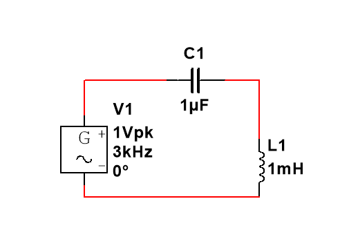
My statement is incorrect. Consider the following \$LC\$ circuit under sinusoidal input: enter image description here

KVL states:

$$V(t) = V_c(t) + V_l(t)$$ $$V(t) = \frac{q}{C} + L \frac{di}{dt} \implies V'(t) = A\sin(\omega t) = Li''+\frac{i}{c}$$

The general solution to ODE is:

$$i(t) = i_h(t)+i_p(t)$$

\$i_p(t)\$ is of the form \$C_1 \sin(\omega t) + C_2 \cos(\omega t)\$

and \$i_h(t)\$ is of the form \$C_3 \sin(\omega_x t) + C_4 \cos(\omega_x t)\$,

where \$\omega_x ^2 = \frac{1}{LC}\$.

Thus,

$$i(t) = C_1 \sin(\omega t) + C_2 \cos(\omega t) + C_3 \sin(\omega_x t) + C_4 \cos(\omega_x t)$$

which is not the sinusoid of the same frequency as input.

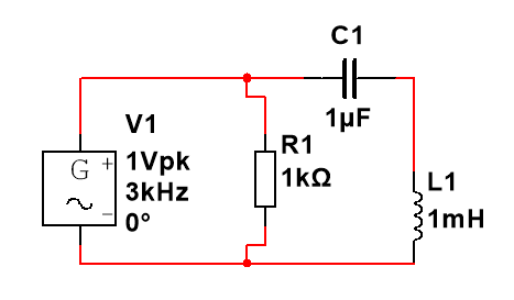
The requirement about having a resistor is still not sufficient since we can have a resistor in parallel like that:

enter image description here

which wouldn't change anything.

In fact, this circuit is not even BIBO stable! That is because we can choose the circuit paramenters to cause resonance.

\$\endgroup\$

Your Answer

By clicking “Post Your Answer”, you agree to our terms of service and acknowledge you have read our privacy policy.

Not the answer you're looking for? Browse other questions tagged or ask your own question.