2
\$\begingroup\$

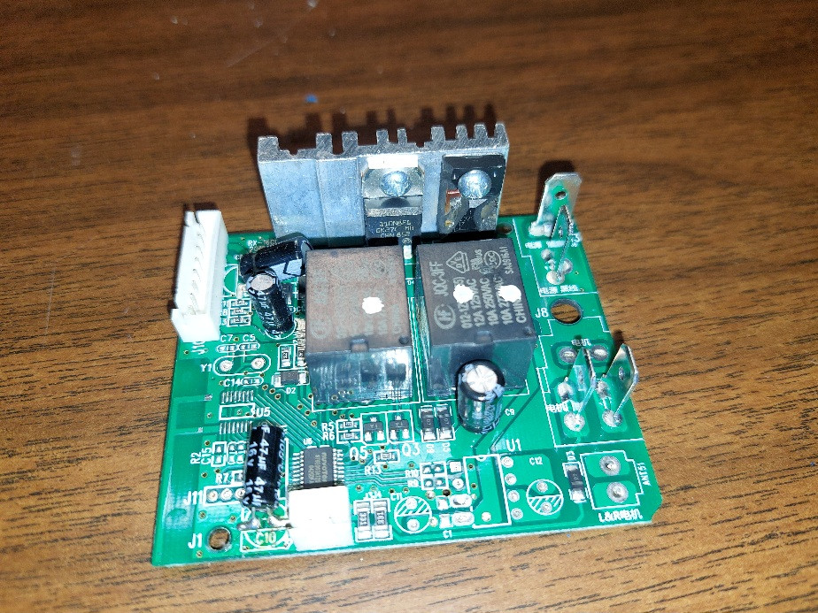
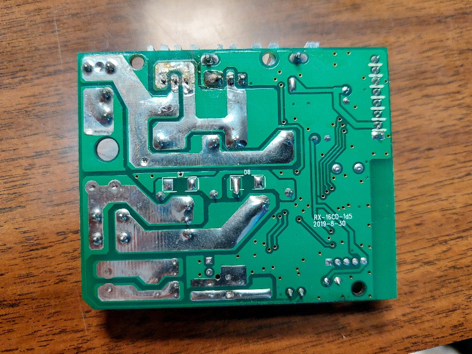
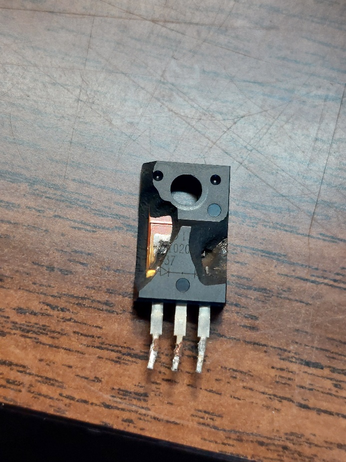
I have a children's electronic ATV that I'm trying to repair. It shuts off whenever power is sent to the wheels (even if the motors are disconnected) and the troubleshooting led me to examine the circuit board that runs everything. When I opened it up, I found that one of the transistors had exploded and burnt out. I was hoping to replace it or the entire board, but I can't figure out what the transistor is exactly and the code printed on the board, RX-16CD-1d5, doesn't return anything useful. Can anyone else identify it?

The model code of the ATV is W442-A06-WH and a link to the manual is here: ATV User Manual

Exploded transistor.

Image of the circuit board from above.

Image of the circuit board from below.

\$\endgroup\$
4
  • 7
    \$\begingroup\$ Are you sure it's a transistor? What's left of the marking seems to indicate a dual diode. \$\endgroup\$
    – Hearth
    Commented Feb 3 at 17:26
  • \$\begingroup\$ I agree with what @Hearth said about appearing to indicate a dual diode. From the tracks shown on PCB pins 1 and 3 on the device are connected together, which from the partial marking are probably be the anodes of the each of the dual diodes, with pin 2 (center) being connected to the the cathode of both diodes. \$\endgroup\$ Commented Feb 3 at 17:33
  • 1
    \$\begingroup\$ Agree with Hearth and Chester, but it's also unlikely that the diode is the only thing damaged, so just replacing it might not be the only thing you need to do. Unless you're very lucky :) Damage like that generally means something pretty destructive happened, that probably impacted other components. (Even if you can't see obvious damage.) It looks like a simple PWM controller with the dual diode as a flyback maybe, so it's worth a shot replacing it. If you can't find the P/N look at the battery voltage and the motor current and pick a diode suitable for handling those with some derating. \$\endgroup\$
    – John D
    Commented Feb 3 at 19:28
  • \$\begingroup\$ I’d hazard to guess someone connected the battery backwards or directly to the motor. An old PC power supply might have a similar diode that can be harvested. \$\endgroup\$
    – Kartman
    Commented Feb 4 at 12:10

3 Answers 3

0
\$\begingroup\$

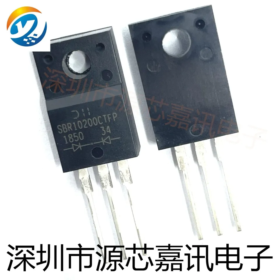
Looks like remnants of a Diodes, Inc. logo, something -1020-, and a common-cathode dual rectifier. Package is TO-220FP. Perusing likely suspects, this may be it:

SBR10200CT–SBR10200CTFP Datasheet | Diodes, Inc.

Compare the photo here,
enter image description here

From: 5PCS New (SBR10200CTFP TO-220F 10A220V) #A6-4 | eBay

Given the description and appearance, it seems likely this is a buck converter, and the only reason the diode should fail is due to overheating. The heatsink isn't very substantial, so that is a possibility; but the mode of failure (both dies blown to h*ck) can only be propelled by fault current. I can conclude the transistor is dead as well, and perhaps by extension, drive circuitry.

I would need a clear, square photo of both sides of the board (probably with major components removed besides) to conclude what the full circuit/layout is, but it looks like the two terminals beside the heatsink are power / battery, and the pair midway along the side are the motor terminals; two SPDT relays provide reversing function, and the buck converter is low-side common, bucking towards +V (which is fine as the motor is a floating load). Notably there is no bypass capacitor (or at least one large enough to handle switching an ATV's motor) near the battery terminals, so the switching cannot be too fast, or the battery cable too long; and I don't see any current sensing, and temperature sensing is highly unlikely, so the controller (U6 is probably a microcontroller, probably set up to run PWM into the transistor, with some input levels, switching or other communcations from the header connector, and no further controls or limits) cannot protect the circuit against over-current or over-temperature conditions.

I would recommend replacing the board with a new one. Possibly, the drive circuitry is okay and replacement diode and transistor will get it going again, but it looks so cheap, it's honestly not worth the effort.

Going up in ratings should be fine; anything 200V, 15-40A rated, schottky or fast-recovery, should do for the diode, and same or lower Rds(on), Qg(tot), and same or higher Vds(max) for the transistor. Voltage ratings must be at least the battery rating plus a safety margin (typically 20-50%), but it's possible they used the extra voltage rating to cheat around the bypass capacitor, and so additional rating is required as-is.

\$\endgroup\$
1
  • \$\begingroup\$ Great, thank you! I was a little worried about the other components being damaged, but I couldn't find any drop-in replacement circuit board online. I will reconsider some of the other boards with additional components online. \$\endgroup\$ Commented Feb 3 at 20:11
0
\$\begingroup\$

Both the surviving symbols at the package and the short between the terminals suggest this is a dual diode.

\$\endgroup\$
0
\$\begingroup\$

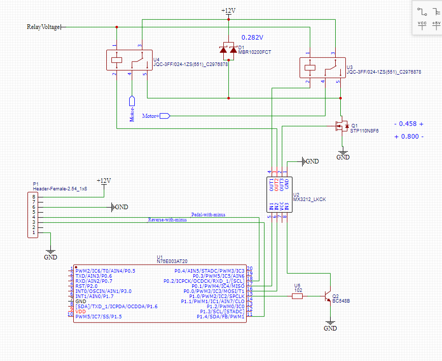
I have the same controller and it's actually MBR10200FCT Schottky barrier rectifier. I was trying to reverse engineer it and still trying to solve the problem why it does not work. Control_Circuit

\$\endgroup\$

Your Answer

By clicking “Post Your Answer”, you agree to our terms of service and acknowledge you have read our privacy policy.

Not the answer you're looking for? Browse other questions tagged or ask your own question.