0
\$\begingroup\$

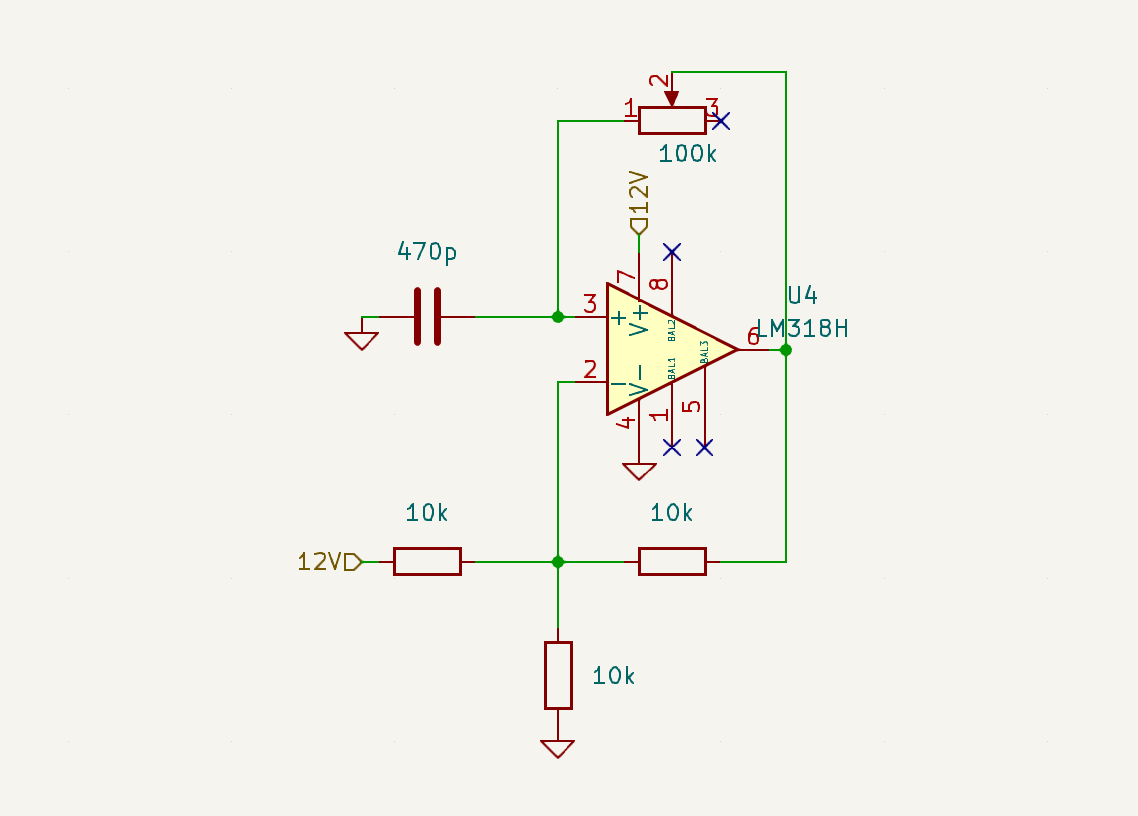
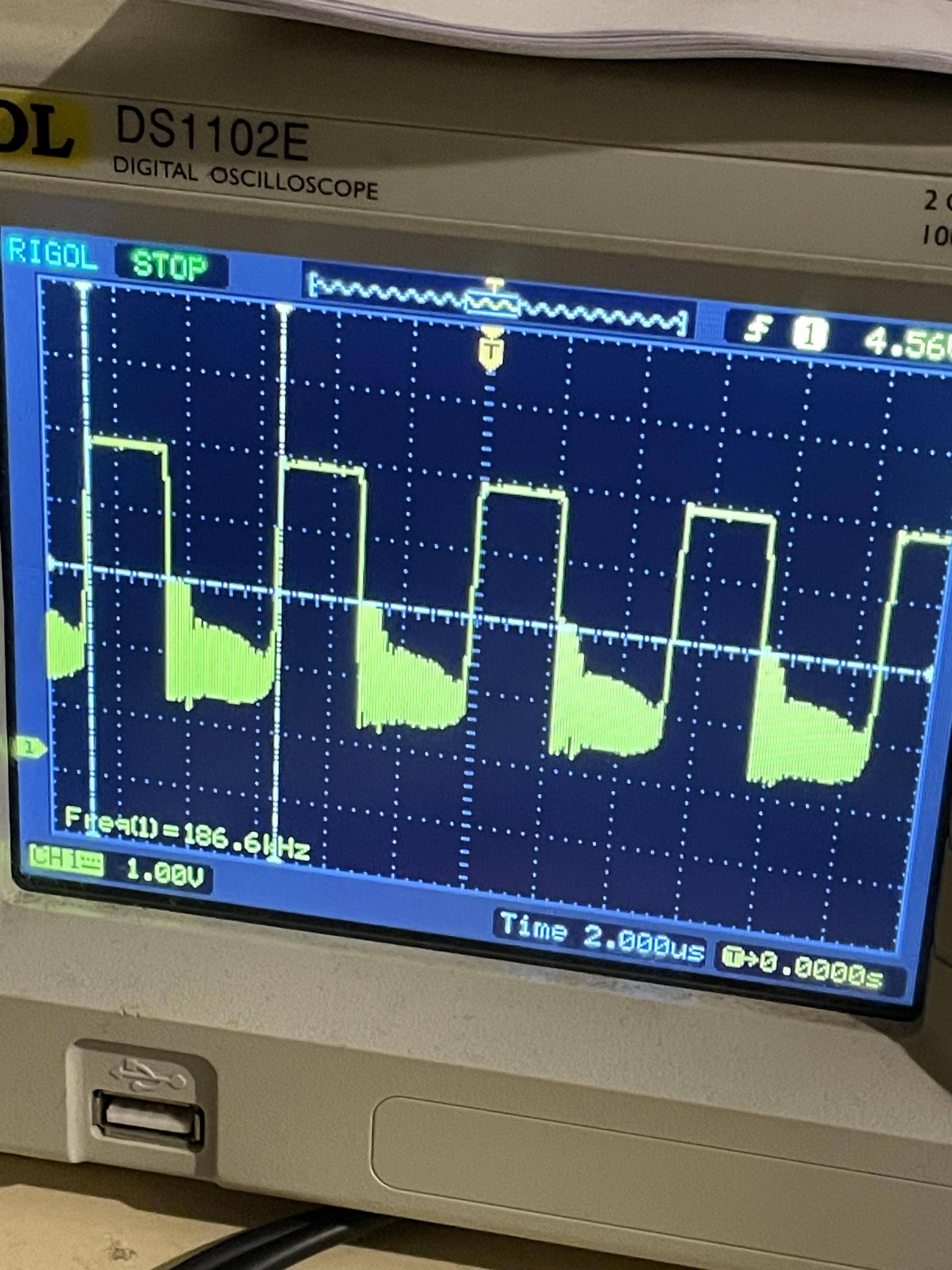
I want to make a 100~200 kHz square wave signal. I tried with a Schmitt trigger oscillator . The circuit below worked well with another op amp but the slew rate was too low so a tried with the LM318 which is faster. But I got this on oscilloscope :

oscillations Do you know what is happening and how to cure it? Here is the schematic: enter image description here

\$\endgroup\$
6
  • 2
    \$\begingroup\$ And your power supply is where? What voltage is it? Single supply or dual supply? And bypass caps are where? \$\endgroup\$
    – Justme
    Commented Feb 3 at 19:39
  • \$\begingroup\$ please add a focused, answerable question to your post \$\endgroup\$
    – jsotola
    Commented Feb 3 at 19:40
  • \$\begingroup\$ @Justme All the components are in the schematic. I've put one bypass cap on the output but nothing had changed. \$\endgroup\$
    – sta
    Commented Feb 3 at 20:27
  • \$\begingroup\$ You need a capacitor from pin 4 to pin 7 near the chip and no capacitor on the output. In fact, put a 100Ω resistor in series with the output (between that and your probe). \$\endgroup\$ Commented Feb 3 at 20:43
  • \$\begingroup\$ @SpehroPefhany thank you it works ! can you tell me more about the probe resistor ? \$\endgroup\$
    – sta
    Commented Feb 3 at 20:52

2 Answers 2

2
\$\begingroup\$

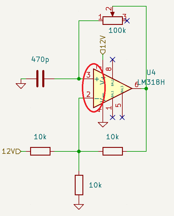
Your op-amp inputs are connected incorrectly for a relaxation oscillator: -

enter image description here

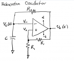
Positive feedback via the 10 kΩ resistors should be to the non-inverting pin like this: -

enter image description here

Image above from here.

You also need op-amp power rail decoupling (a capacitor) and, the capacitor you mention on the output is a no-no.

\$\endgroup\$
1
  • 1
    \$\begingroup\$ Yes i made a mistake in the schematics but the real circuit was good. the problem was really the decoupling capacitor and a resistance between the probe and the output. Thank you! \$\endgroup\$
    – sta
    Commented Feb 3 at 21:08
2
\$\begingroup\$

You need a capacitor from pin 4 to pin 7 near the chip and no capacitor on the output (also inverting and non-inverting are switched, but that was a transcription error you said).

In fact, put a 100Ω resistor in series with the output (between that and your probe).

The decoupling capacitor prevents inductance in your power supply leads from resulting in imperfect power to the chip when there are fast changes in demand from the chip. One way you can cause such a rapid demand is to add a capacitor to the output. If it's set up as an amplifier, that will likely cause oscillation unless the capacitor is tiny (100pF is usually safe, but not necessarily for micropower op-amps). As a comparator it will cause big surges from the supplies.

A small series resistor between the output and whatever it might be driving (but not in series with the feedback) that is capacitive (such as a x1 oscilloscope probe or a cable with significant capacitance) can help prevent that kind of problem.
\$\endgroup\$

Your Answer

By clicking “Post Your Answer”, you agree to our terms of service and acknowledge you have read our privacy policy.

Not the answer you're looking for? Browse other questions tagged or ask your own question.