2
\$\begingroup\$

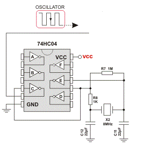
I've build a circuit exactly like the one below except Im using a SN74HC14N (schmitt triggered inverter).

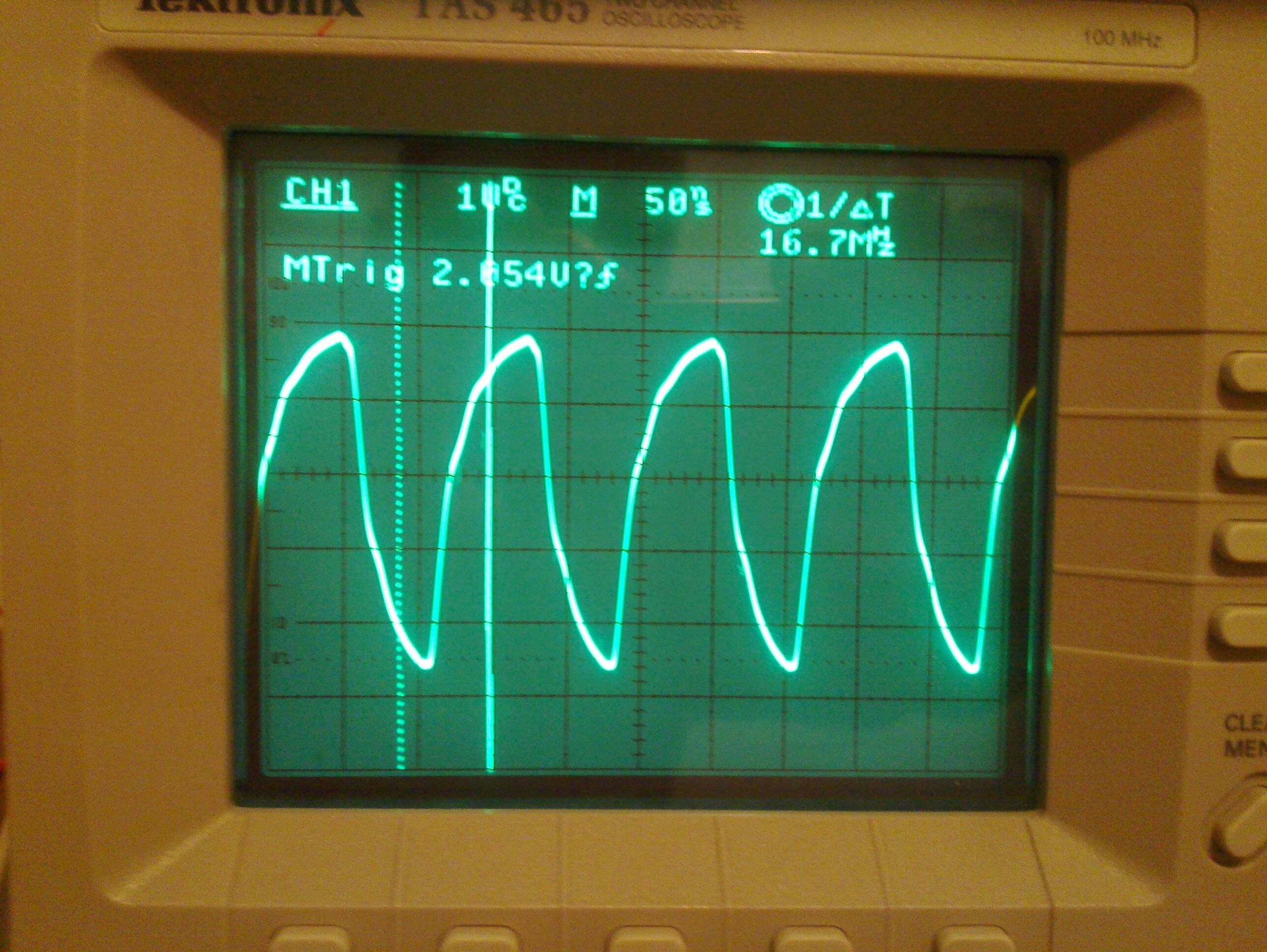
The output of the circuit looks like this, however isnt it supposed to be more square wave looking? I've tried feeding the output to another schmitt triggered not gate but the output stays the same. Anyway to get a more square wave looking output?

Also when I used non schmitt triggered not gates there was no output at all. All the gates im using are TTL. The crystal is 8mhz, and my oscilloscope goes up to 100mhz
There is a similar question. However, my oscillator is based on a pierce circuit

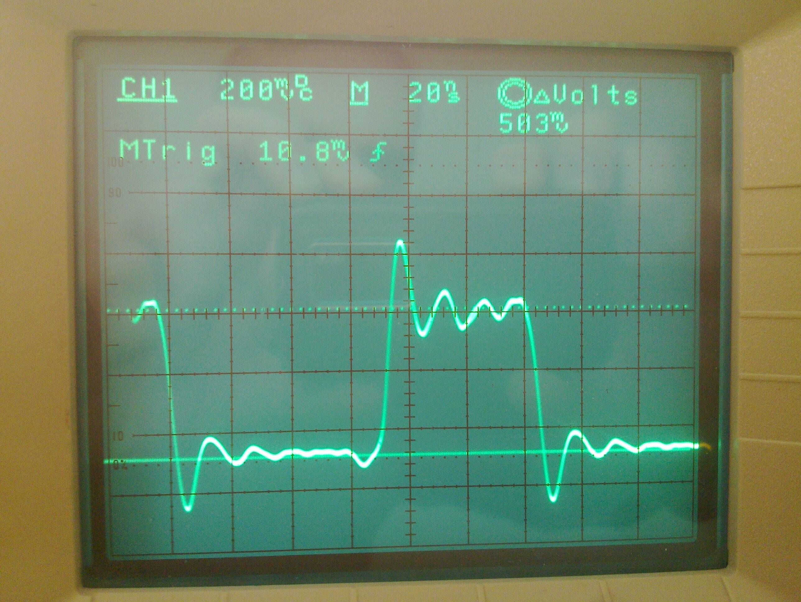
Edit: Here is what I get when I set the probe to 10x, I guess this is acceptable? even if it spikes? 10x reading
\$\endgroup\$
7
  • 2
    \$\begingroup\$ What are you test leads and how is the circuit constructed? \$\endgroup\$
    – Matt Young
    Commented Feb 17, 2013 at 0:48
  • \$\begingroup\$ A photograph of the physical circuit could help us give you a good answer. Also, what's your Vcc? \$\endgroup\$
    – The Photon
    Commented Feb 17, 2013 at 0:53
  • 3
    \$\begingroup\$ Especially, what's your VCC? I'm seeing rise and fall times of 38ns @ 2V according to a databook. But also : is this measured using a correctly compensated x10 scope probe? \$\endgroup\$
    – user16324
    Commented Feb 17, 2013 at 1:10
  • 2
    \$\begingroup\$ Another vote for an incorrectly compensated probe here. \$\endgroup\$
    – Matt Young
    Commented Feb 17, 2013 at 4:24
  • \$\begingroup\$ VCC is 5v, and no my probe is on 1x should it be on 10x? \$\endgroup\$
    – RMDS
    Commented Feb 17, 2013 at 16:46

1 Answer 1

3
\$\begingroup\$

When switching to a 10X probe I am now seeing a high quality signal. The probe was the issue the entire time.

This issue is resolved.

\$\endgroup\$
5
  • 1
    \$\begingroup\$ I suspect the ringing on your waveform is due to the ground connection. Are you using a normal probe ground lead which can be 6 inches or more? If so, reduce it to less than an inch and the ringing should decrease considerably. \$\endgroup\$
    – Barry
    Commented Feb 17, 2013 at 22:07
  • \$\begingroup\$ You should make this a comment or an edit on the original question. The answer section is for answers to your question. You are allowed and encouraged to provide an answer to your own question, but this is not it. \$\endgroup\$ Commented Mar 19, 2013 at 20:14
  • 1
    \$\begingroup\$ @PabloMaurin - by all appearances, the poster probably considered this the resolution of the issue - ie, an answer. Likely there's more going on - compensation and/or transmission lines, but they may not care or need to. \$\endgroup\$ Commented Mar 19, 2013 at 20:36
  • \$\begingroup\$ I have edited your answer assuming you mean this to be an answer(it read the same to me as @chrisstratton). can you please clarify your circuit and setup, maybe pictures of your setup, someone might be able to correct your entire issue. \$\endgroup\$
    – Kortuk
    Commented Mar 19, 2013 at 22:24
  • \$\begingroup\$ I had this same problem. Reducing the ground loop made a significant change. \$\endgroup\$ Commented Sep 18, 2020 at 21:07

Your Answer

By clicking “Post Your Answer”, you agree to our terms of service and acknowledge you have read our privacy policy.

Not the answer you're looking for? Browse other questions tagged or ask your own question.