The way you want to do it won’t work. The optocouplers don’t switch equally fast and will fail due to overvoltage.
Use a single optoisolator and a cascode. The cascode in this case is the NPN transistor Q1 in the collector circuit of the optoisolator. Set the base of that transistor at say 1V. In the example, two diodes do this approximate job. When the optoisolator is off, there is no current flowing from emitter of Q1 to ground, and the Q1 collector C floats to high voltage. When the optocoupler is on, current flows through the Q1, and its collector C is pulled down to less than 1V.
The voltage on the collector of the optocoupler is always between 0 and 2V, well within its ratings.
The cascode also speeds up the optocoupler's output transitions, since the Miller effect is vastly reduced, as the collector voltage changes very little compared to what it'd do without the cascode. Thus, the Miller capacitance doesn't need to get charged/discharged as much as it otherwise would.
D1 provides reverse B-E voltage protection to the cascode transistor. D2 and D3 set the cascode's base potential. R1 sources the current to establish the voltage across D2 and D3, as well as providing the base current for Q1.
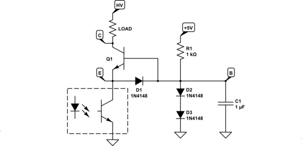
simulate this circuit – Schematic created using CircuitLab
The board house may be more likely to have a high-voltage N-MOS available than a high-voltage BJT, so you can use that instead:
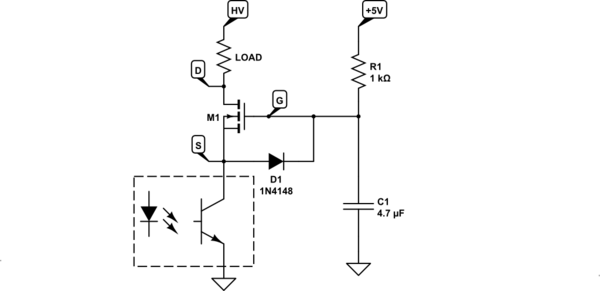
simulate this circuit
The operation is analogous, but the gate voltage needs to be substantially higher than the base voltage. High-voltage mosfets have fairly high threshold voltages relative to 0.7V VBE of a BJT. Select a mosfet that can fully turn on with the G-S voltage a bit lower than a low voltage supply voltage you have available.
The gate current is minuscule, so you're free to use voltage multipliers to generate the gate voltage from a logic supply voltage:
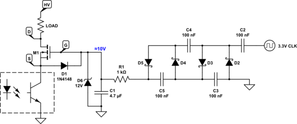
simulate this circuit
D6 protects the gate and logic from transients. C2..C5,D2..D5 are a voltage quadrupler cascade. With a 3.3V square wave input of 1kHz or so, it will output at least 10V. The parts in the quadrupler are not critical, except the capacitors must be rated for 25V at least. 0.1μF/50V parts will be fine. Even the cheapo Y5Z dielectric will work well enough, as opposed to X5R or X7R you generally should be generally using to avoid loss of capacitance with DC bias. The low-voltage square wave can come from a GPIO, a CMOS 555, etc.
I'm working with the sub-set parts the PCB assembler house has pre-loaded, and not what is commercially available. Like using 3-6 resistors in place of 1, and more relevant to this question; series-ing capacitors with balance resistors to raise the maximum voltage specification.
That’s the prime example of “penny wise, pound foolish”. You’ll waste so much time fixing the problems due to this “optimization” that paying the minuscule price of loading extra parts will actually save you money. Forget about this “stacking the parts” “savings”. It’s a terrible idea. Really is.
The cascode is a good way of adapting optocouplers to higher collector voltages - most optocouplers have collector voltage ratings under 100V, so that makes sense. It will work reliably since the cascode transistor is rated for the full output voltage. As opposed to stacking under-rated parts.
small order jobs (20-30 boards)
In spite of the small order, you can approximately budget an hour of your time, with all overheads, to cost the business about $20-$150, depending on where in the world you are, and what's your experience level. How many hours of your messing about will it take to wipe any "savings"?
This calculus is different for hobby projects, of course. But in a business setting, quite often the simplest if more expensive way may well cost much less than the "cheapest" way that involves more engineering time.
think static lightning charges
You'll be paying for stuffing less common parts for overvoltage protection anyway. You may look for a cheaper board house if you wish. Or decide that stuffing a few parts yourself, if you're well equipped for that, may cost as much as board house expense. You'd need to have a proper workstation for that, proper flux(es), an ultrasonic board cleaner, proper technique, and so on. So it may be really a good deal to pay the board house to do it.
I could buy Renesas PS2913-1-V-F3-AX which is a 120V part
That's not a high enough rating if you expect 150V transients. A 120V-rated transistor should be used with max 100V on the collector, to be conservative. If the circuit is expected to run hot (in an enclosure exposed to sunlight), even more derating is needed, say 60% of rated voltage. In hot conditions you'll also want to derate the optocoupler significantly. I'd generally not run optocoupler LEDs higher than 50% rated LED current in room temperature environment, and maybe 20% when the enclosure is in sunlight.
I'm not sure what currents need to be switched by the optocoupler, and what CTR (current transfer ratio) parts are available at the board house. Assuming cheapo 100% CTR worst-case optocouplers, you may have just a couple mA of collector current available. You'd then need to use an external transistor to boost the current if driving a bipolar cascode, or use an inverter configuration if driving a mosfet cascode.

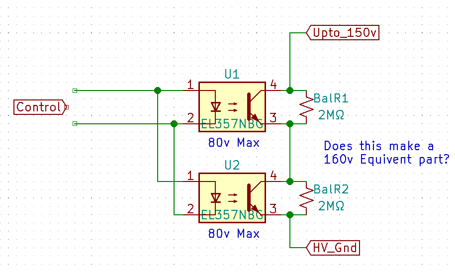


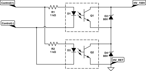
lightningcharges, and other outdoor hazards. Directly connected would be the Gate of a P-fet, but with added protection of the Fet pins, so that any over-volt would pass by and on to this control element. Thus the Control (this Optocoupler) can be exposed to ~90v \$\endgroup\$