8
\$\begingroup\$

Yet again I'm working with the sub-set parts the PCB assembler house has pre-loaded, and not what is commercially available. Like using 3-6 resistors in place of 1, and more relevant to this question; series-ing capacitors with balance resistors to raise the maximum voltage specification.

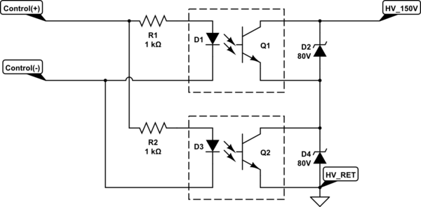
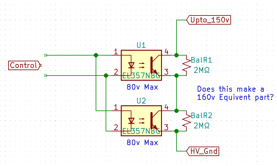
Can you do this with optocouplers in a series stack, with or without balance resistors?

enter image description here

My example is two Everlight EL357 which is a 80V part. It costs about 5½¢ (0.055USD) and is pre-loaded at my assembler.

My use is in a system where the over-volt protection begins at 90V, so for parts that are externally exposed, I want 120V limits or higher (150V being common.)

I could buy Renesas PS2913-1-V-F3-AX which is a 120V part, but it costs $2.23, then add shipping, add storage cost at the assembler, and a per-job load-fee for non pre-loaded parts. This will easily get the part to the $5 range for small order jobs (20-30 boards.)

There are also other types of optocouplers, but my board house only has 4 preloaded and they are all the transistor output type, so the same problem as a Renesas if I were to switch types.

So $5.00 or $0.11? This is why I ask these questions.

\$\endgroup\$
5
  • \$\begingroup\$ What's connected to the "Upto_150V" node? \$\endgroup\$ Commented Feb 15 at 14:31
  • \$\begingroup\$ @JonathanS. long incoming transmission line, so think static lightning charges, and other outdoor hazards. Directly connected would be the Gate of a P-fet, but with added protection of the Fet pins, so that any over-volt would pass by and on to this control element. Thus the Control (this Optocoupler) can be exposed to ~90v \$\endgroup\$ Commented Feb 15 at 14:46
  • 3
    \$\begingroup\$ "Yet again I'm working with the sub-set parts the PCB assembler house has pre-loaded, and not what is commercially available." ... why? \$\endgroup\$
    – Attie
    Commented Feb 15 at 15:33
  • 1
    \$\begingroup\$ @Attie, "why" because for a small business, with only 4 employees (owner, secretary, ladder-climber, and me) that is non-electronics service provider, making electronics is not what we do. We make electronics to make our real job easier/possible/reliable. Pre-loaded parts are really the only financially realistic way to get hardware built, as a small business. \$\endgroup\$ Commented Feb 15 at 20:32
  • 14
    \$\begingroup\$ i'm honestly mystified by the idea of a business where electronics are non-essential part of it yet you need to a couple dozen boards for in-house use but are constrained by specific parts that a PCB assembler has where the total savings if you hack some other solution is on the order of 100 bucks. That just screams x-y problem. \$\endgroup\$
    – eps
    Commented Feb 16 at 0:02

4 Answers 4

22
\$\begingroup\$

The way you want to do it won’t work. The optocouplers don’t switch equally fast and will fail due to overvoltage.

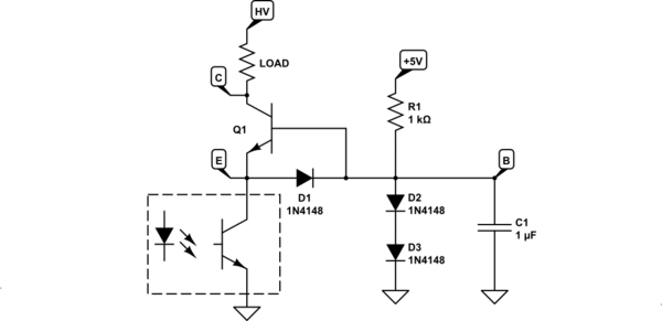
Use a single optoisolator and a cascode. The cascode in this case is the NPN transistor Q1 in the collector circuit of the optoisolator. Set the base of that transistor at say 1V. In the example, two diodes do this approximate job. When the optoisolator is off, there is no current flowing from emitter of Q1 to ground, and the Q1 collector C floats to high voltage. When the optocoupler is on, current flows through the Q1, and its collector C is pulled down to less than 1V.

The voltage on the collector of the optocoupler is always between 0 and 2V, well within its ratings.

The cascode also speeds up the optocoupler's output transitions, since the Miller effect is vastly reduced, as the collector voltage changes very little compared to what it'd do without the cascode. Thus, the Miller capacitance doesn't need to get charged/discharged as much as it otherwise would.

D1 provides reverse B-E voltage protection to the cascode transistor. D2 and D3 set the cascode's base potential. R1 sources the current to establish the voltage across D2 and D3, as well as providing the base current for Q1.
schematic

simulate this circuit – Schematic created using CircuitLab

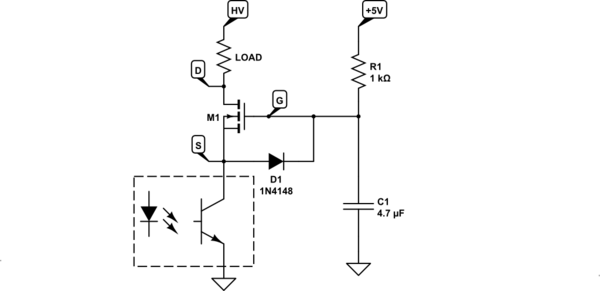
The board house may be more likely to have a high-voltage N-MOS available than a high-voltage BJT, so you can use that instead:
schematic

simulate this circuit

The operation is analogous, but the gate voltage needs to be substantially higher than the base voltage. High-voltage mosfets have fairly high threshold voltages relative to 0.7V VBE of a BJT. Select a mosfet that can fully turn on with the G-S voltage a bit lower than a low voltage supply voltage you have available.

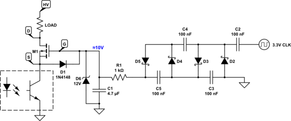
The gate current is minuscule, so you're free to use voltage multipliers to generate the gate voltage from a logic supply voltage:
schematic

simulate this circuit

D6 protects the gate and logic from transients. C2..C5,D2..D5 are a voltage quadrupler cascade. With a 3.3V square wave input of 1kHz or so, it will output at least 10V. The parts in the quadrupler are not critical, except the capacitors must be rated for 25V at least. 0.1μF/50V parts will be fine. Even the cheapo Y5Z dielectric will work well enough, as opposed to X5R or X7R you generally should be generally using to avoid loss of capacitance with DC bias. The low-voltage square wave can come from a GPIO, a CMOS 555, etc.

I'm working with the sub-set parts the PCB assembler house has pre-loaded, and not what is commercially available. Like using 3-6 resistors in place of 1, and more relevant to this question; series-ing capacitors with balance resistors to raise the maximum voltage specification.

That’s the prime example of “penny wise, pound foolish”. You’ll waste so much time fixing the problems due to this “optimization” that paying the minuscule price of loading extra parts will actually save you money. Forget about this “stacking the parts” “savings”. It’s a terrible idea. Really is.

The cascode is a good way of adapting optocouplers to higher collector voltages - most optocouplers have collector voltage ratings under 100V, so that makes sense. It will work reliably since the cascode transistor is rated for the full output voltage. As opposed to stacking under-rated parts.

small order jobs (20-30 boards)

In spite of the small order, you can approximately budget an hour of your time, with all overheads, to cost the business about $20-$150, depending on where in the world you are, and what's your experience level. How many hours of your messing about will it take to wipe any "savings"?

This calculus is different for hobby projects, of course. But in a business setting, quite often the simplest if more expensive way may well cost much less than the "cheapest" way that involves more engineering time.

think static lightning charges

You'll be paying for stuffing less common parts for overvoltage protection anyway. You may look for a cheaper board house if you wish. Or decide that stuffing a few parts yourself, if you're well equipped for that, may cost as much as board house expense. You'd need to have a proper workstation for that, proper flux(es), an ultrasonic board cleaner, proper technique, and so on. So it may be really a good deal to pay the board house to do it.

I could buy Renesas PS2913-1-V-F3-AX which is a 120V part

That's not a high enough rating if you expect 150V transients. A 120V-rated transistor should be used with max 100V on the collector, to be conservative. If the circuit is expected to run hot (in an enclosure exposed to sunlight), even more derating is needed, say 60% of rated voltage. In hot conditions you'll also want to derate the optocoupler significantly. I'd generally not run optocoupler LEDs higher than 50% rated LED current in room temperature environment, and maybe 20% when the enclosure is in sunlight.

I'm not sure what currents need to be switched by the optocoupler, and what CTR (current transfer ratio) parts are available at the board house. Assuming cheapo 100% CTR worst-case optocouplers, you may have just a couple mA of collector current available. You'd then need to use an external transistor to boost the current if driving a bipolar cascode, or use an inverter configuration if driving a mosfet cascode.

\$\endgroup\$
1
  • \$\begingroup\$ Yes, the board house has a N-fet 150v part, and that is my current design, but the 5V to power it is added complexity I was trying to avoid. I'm also very small power budgets (like can't use a Diode). My currents are low (fet gate drive) and my switching frequency is in DAYS. I'm running the LED at 5mA. Also as stated in above, I'm expecting 90v transients so I want a 120v or 150v part. The Part is the 'B' version so a CTR of 130-260, but I'm just using it as a switch to the current gain isn't important as I don't wan to burn much current on the transistor side either. Thanks \$\endgroup\$ Commented Feb 15 at 20:14
5
\$\begingroup\$

TLDR: I'd not be tempted to do this.

Although max breakdown voltage for EL357 is 80V, reverse breakdown is only 7V.
Convincing yourself that those two 2M balancing resistors will make these two devices share equally the voltage load is foolishness.

At best, when these devices turn on or off, their current transfer ratio spans 2:1 range. So when they're in transition, you can bet that they won't share the load equally.
And driving the LED side in parallel further compromises current-sharing.

\$\endgroup\$
1
  • 3
    \$\begingroup\$ I’m certain it will fail in short order, so it’s less of a “temptation” than “penny wise, pound foolish”. The asker is already wasting time asking questions about “money saving workarounds”. Their time must be very cheap if they can afford that instead of having right components loaded at the board house… \$\endgroup\$ Commented Feb 15 at 14:53
4
\$\begingroup\$

You can make this work. But it would be a poor design. An improvement (but still a poor idea) would be to mod your circuit like this:

schematic

simulate this circuit – Schematic created using CircuitLab

You won't get any additional isolation from HV to control using 2 optos instead of 1. Also, you have very little margin for error regarding device tolerancing - this is not a robust.

\$\endgroup\$
3
  • 1
    \$\begingroup\$ Is the board house more likely to have an 80V Zener on the reel, or a HV transistor or mosfet? \$\endgroup\$ Commented Feb 15 at 15:10
  • 2
    \$\begingroup\$ @Kubahasn'tforgottenMonica I couldn't tell you. I design my circuits based on what the circuit needs to function properly and make sure the board shop procures appropriate parts. I don't design my boards based on "what the PCB machine already has reeled up" :-) \$\endgroup\$
    – MOSFET
    Commented Feb 15 at 15:17
  • \$\begingroup\$ @MOSFET I wish had that luxury. Every intern we hire says stuff like that. I did too originally. It really is amazing what you can accomplish with these limitation. We are a small company (4 employees) and its not an electronics firm. We just make equipment for internal use, that we can't buy, or what you can buy is too failure prone. \$\endgroup\$ Commented Feb 15 at 20:21
2
\$\begingroup\$

It might work. I agree with others that the transistors will likely experience breakdown under some conditions.

Vce breakdown in BJTs is non-destructive if the current is limited, but it's far from clear it will be sufficiently limited. The resistors may not even have much effect. You could add reverse biased diodes across each.

Unless you can test this adequately, I'd give this a hard pass and either have the PCBA house install properly spec'd parts or add them after they arrive.

\$\endgroup\$

Your Answer

By clicking “Post Your Answer”, you agree to our terms of service and acknowledge you have read our privacy policy.

Not the answer you're looking for? Browse other questions tagged or ask your own question.