0
\$\begingroup\$

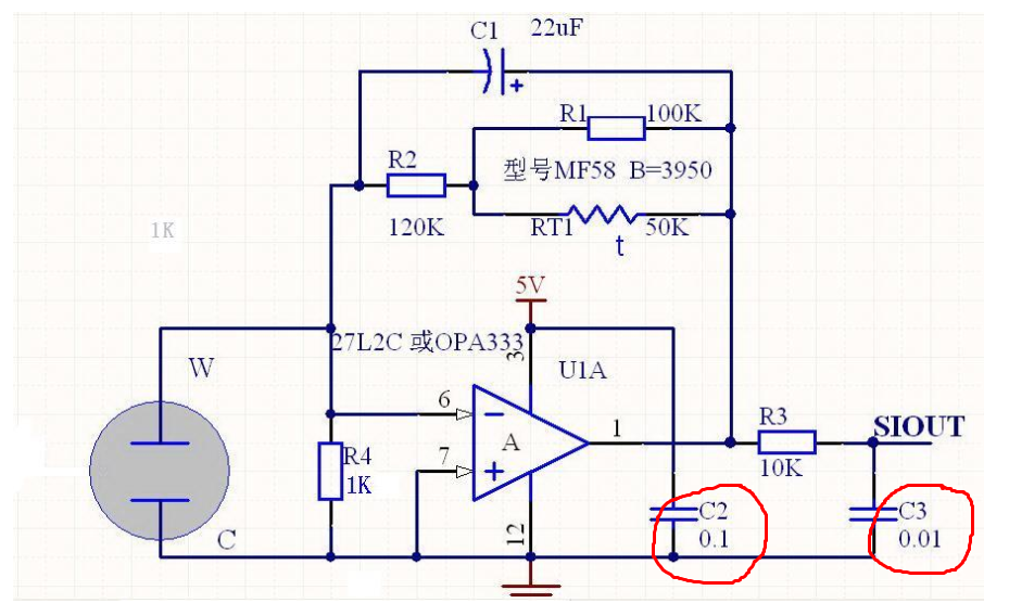
I got this schematic in the manual of the gas sensor provider. The sensor is Winsen ME2-C2H5OH-Ф16. The schematic is the application circuit for reading the fuel cell sensor, using an op-amplifier. Everything is clear however there are 2 capacitors C2 & C3 does not mention enough unit value.

I asked the sale woman, she said uF, but I don't think she is a technical person.

Please can anyone tell me how to calculate or confirm the correct value? Thanks.

Circuit schematic of the op-amp for sensor

\$\endgroup\$
3
  • 1
    \$\begingroup\$ All the capacitor values in the schematic are in µF. That greek letter is bad to reach on many keyboard languages. \$\endgroup\$
    – Turbo J
    Commented Apr 18 at 12:05
  • \$\begingroup\$ @TurboJ They managed to type 22uF for C1. So it is not about keyboards or locale, it's just a sloppy schematic. The resistors have temperature rating in Kelvin too, apparently... 1K is pretty darn cold. \$\endgroup\$
    – Lundin
    Commented Apr 18 at 13:29
  • \$\begingroup\$ Almost everybody writes R (Ohms) or K (kilo Ohm) for resistor values in a schematic. Google some more complex ones on the internet as example. \$\endgroup\$
    – Turbo J
    Commented Apr 18 at 20:00

2 Answers 2

0
\$\begingroup\$

I'm pretty sure C2 is 0.1 μF (100n) and C3 0.01 μF (10n). It's really unlikely to use 0.1 F or 0.1 pF or 0.1 nF or 0.1 fF capacitor as the only supply decoupling cap for an op amp.

Though, the C2 might be there to keep the circuit alive for some time when the power is gone, in this case a 0.1F (e.g. 100 mF super cap) would make sense. We don't see the rest of the circuit, we don't know what this circuit does (or is for), so hard to make a guess.


I asked the sale woman, she said uF

Yes, it's common to select the base unit for capacitors as μF. Nevertheless, I'd expect a note somewhere in the document, saying something like

All capacitors are in microfarads (μF) unless otherwise specified.

But the problem is, the C1 on top has "22 uF" instead of "22".

\$\endgroup\$
0
\$\begingroup\$

They are in uF for sure.

There is nothing much to calculate for C2, it is a bypass capacitor and 1uF would work at least as well, and probably 0.01uF as well, given that U1 is a really, really slow micropower op-amp (350kHz GBW).

R3 and C3 form a low-pass filter with a cutoff frequency of 1.6kHz, which is too high to help with mains noise. It's not entirely clear to me why they have added that, but it does no harm unless then 10kΩ source resistance causes problems with whatever is connected to the output. Possibly just to prevent problems with long lead lead lengths to a sensor circuit. Again, 10uF or 1uF would work since the inherent sensor response time is double-digit seconds.

\$\endgroup\$

Your Answer

By clicking “Post Your Answer”, you agree to our terms of service and acknowledge you have read our privacy policy.

Not the answer you're looking for? Browse other questions tagged or ask your own question.