0
\$\begingroup\$

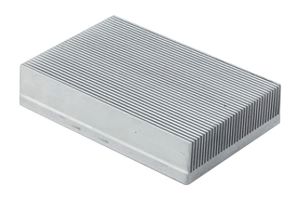
I want to mount multiple PCB-mounted TO-247 devices to a single large heatsink, something comparable to this:
enter image description here

My devices may or may not have mounting holes through them, and their tabs may or may not be isolated. Any approach will have to support the use of mounting clamps and isolation pads. I'm using TO-247 devices for cost reasons; the smallest chassis-mount devices I'm aware of are SOT-227, which cost much more than similar parts in TO-247 packages.

What approaches to this problem are used? What difficulties are presented by those approaches?

\$\endgroup\$
2
  • \$\begingroup\$ Can it still be called TO-247 without the mounting holes? \$\endgroup\$
    – Kaz
    Commented Jun 3, 2013 at 21:38
  • \$\begingroup\$ I wouldn't use this kind of package if you need to attach a big heatsink like that. I would use some packege SMD. Everything would be easier. Anyway, here you have some advices for heatsink attach to TO247. ti.com/lit/an/snoa460/snoa460.pdf \$\endgroup\$ Commented Jun 4, 2013 at 13:15

3 Answers 3

2
\$\begingroup\$

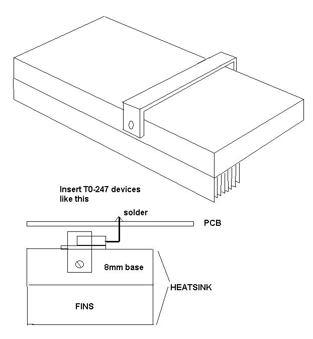
I did this once: - enter image description here

Use a strap of sturdy metal to push the transistors down onto the base of the heatsink.

You'll need to drill holes in the sides of the heatsink to hold the strap in place.

Legs of transistors point upwards and solder into PCB.

Transistors and PCB can be removed from the heatsink by undoing screws holding strap.

\$\endgroup\$
9
  • \$\begingroup\$ Was this on something mass-produced? If so, how did you handle getting the legs of the devices to line up with the circuit board holes properly? \$\endgroup\$ Commented Jun 3, 2013 at 17:47
  • \$\begingroup\$ Easy - the transistors were already soldered to the board and bent into shape - the exact pattern they formed under the strap wasn't precise but they didn't need to be. The circuit board then screwed down (on pillars) to the heatsink on seperate holes. The beauty of this is that you undo the pcb mounts, undo the two strap mounts and the assembly is free of the heatsink. You can even test it without the heatsink with light loads. There was a one-piece insulator that fitted under all transistors too. \$\endgroup\$
    – Andy aka
    Commented Jun 3, 2013 at 19:25
  • \$\begingroup\$ I've done something similar for a board that had TO-220 devices mounted to in from the bottom side. In my case the board was smallish and had two devices. I added clearance holes in the board itself to permit the passing of a hex head machine screw through the hole to secure the TO-220 device to the heatsink. The heatsink plate was drilled and tapped with threads to accept the machine screw. A magnetic T-Handle hex wrench easily guided the screw through the hole and into the plate. The board mounted onto several standoffs that were press fitted into the heatsink plate. \$\endgroup\$ Commented Jun 3, 2013 at 20:31
  • \$\begingroup\$ @Andyaka What about the mechanical stress? As far as I understand, in your proposal the TO legs will be withstand all the mechanical stress moreover, the heatsink seems really heavy. \$\endgroup\$ Commented Jun 4, 2013 at 8:47
  • \$\begingroup\$ @JesúsCastañé The PCB is also screwed down (on pillars) - this takes all the stress. See "Easy" comment above. Why does the heat-sink seem heavy - do you have one in your hands? \$\endgroup\$
    – Andy aka
    Commented Jun 4, 2013 at 9:16
0
\$\begingroup\$

A few ideas present themselves.

  1. Mount the devices perpendicular to the PCB, at the edge of the PCB, and mount the PCB perpendicular to the heatsink. This can pose difficulties in high-vibration environments or shipping, requiring more mechanical stabilization of the PCB itself. It also enforces an effective size limit on the PCB, and puts stricter limits on the layout of the board.
  2. Mount the devices parallel to the PCB, with the device tabs hanging off the edge of the board (or a hole therein). This means that either the PCB must be directly in the plane of the top of the sink (not an option in some chassis designs), or there must be a metal block between the devices and the sink proper.
  3. Mount the devices directly to the sink under the PCB, and bend the legs upward to solder into the board. This makes assembly more difficult. Holes must be left in the PCB to access mounting clamps.

In all cases, isolation pads are needed between the device legs and the sink, to maintain clearances at high voltages.

\$\endgroup\$
0
\$\begingroup\$

You have to drill and tap holes for screws that fit within maximum hole diameter of 3.91 mm (0.154") Each screw may use a plastic washer to provide more tolerance to excess torque. Each device needs a good thermal conducting electrical insulating pad.

Some designs use spring metal clips for ease of installation which are screwed into the heatsink but have the force of a heavy duty paper clip in a small size.

Choose devices that limit the heat dissipation is the 1st step by low RdsON or serries drop voltage. Consider CPU heatsinks with custom mounting holes added but in a smaller package with a low RPM fan with edge mount PCB strips on either side using a jig for assembly.

\$\endgroup\$

Not the answer you're looking for? Browse other questions tagged or ask your own question.