0
\$\begingroup\$

I'm trying to make UART connection to Atmega328p from HW-199 UART module. Here's my code:

static void UartPutChar(char ch)
{
    while (!(UCSR0A & (1 << UDRE0)));
    UDR0 = ch;
}

static void UartPutString(const char* str, uint32_t size)
{
    for (uint32_t i = 0; i < size; i++) {
        UartPutChar(str[i]);
    }
}


static char UartReceiveChar(bool echo)
{
    while (!(UCSR0A & (1 << RXC0)));
    char ch = UDR0;
    if (echo) {
        UartPutChar(ch);
    }
    return ch;
}

static uint8_t UartReceiveString(char* str, uint8_t maxLen, bool echo)
{
    uint8_t i = 0;
    char c = 0;

    while (i < maxLen && c != '\n' && c != '\r')
    {
        c = UartReceiveChar(echo);
        str[i] = c;
        i++;
    }
    return i;
}


int main(void)
{
    srand(time(0));

    _NOP();
    CFG_OUTPUT_PDn(PD5);
    SET_LOW_PDn(PD5);

    uint16_t ubrr = (F_CPU / 16 / BAUD) - 1;
    UBRR0H = (uint8_t)(ubrr >> 8);
    UBRR0L = (uint8_t)(ubrr & 0xFF);

    UCSR0B |= (1 << RXEN0) | (1 << TXEN0);

    const char* statusText = "\r\nSTATUS\r\n"
    "Accelerometer data:\r\n"
    "\tX: %d\r\n"
    "\tY: %d\r\n"
    "\tZ: %d\r\n"
    "Gyroscope data:\r\n"
    "\tX: %d\r\n"
    "\tY: %d\r\n"
    "\tZ: %d\r\n"
    "Magnetometer data:\r\n"
    "\tX: %d\r\n"
    "\tY: %d\r\n"
    "\tZ: %d\r\n"
    "Temperature: %d\r\n"
    "Pressure: %d\r\n"
    "Altitude: %d\r\n"
    ;

    char buf[1024] = {0};

    while (1)
    {
        UartReceiveChar(true);
        UartPutString("\r\n", 2);

        memset(buf, 0, sizeof(buf));
        uint32_t len = sprintf(buf, statusText, rand() % 32, rand() % 32, rand() % 32, rand() % 32, rand() % 32, rand() % 32, rand() % 32, rand() % 32, rand() % 32, rand() % 32, rand() % 32, rand() % 32);
        UartPutString(buf, len);
        UartPutString("\r\n", 2);
    }
}

This code outputs a large piece of random data for testing purposes. When I press any key in terminal, it prints system data to the terminal, then the loop goes on and wait for the next key. Everything works good until some moment which causes either UART to drop connection to COM port (error writing to serial device) or it just hangs at some point and I need to reset the MCU, reconnect USB, and terminal and start the program over (losing all RAM data). I don't see any obvious issues with my code, it looks ok. BAUD is set to 4800 in code, putty, and in Windows device manager for UART device. 1 stop bit, 8 data bits, no parity also set by default in putty, Windows device, and Atmega328p initializes needed registers on launch to match this configuration.
What do I do wrong and how to make UART messaging not causing everything to stuck?

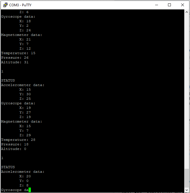
Here is a moment when it gets stuck. Terminal doesn't respond to my keystrokes, Tx/Rx LEDs of the UART are not lit enter image description here
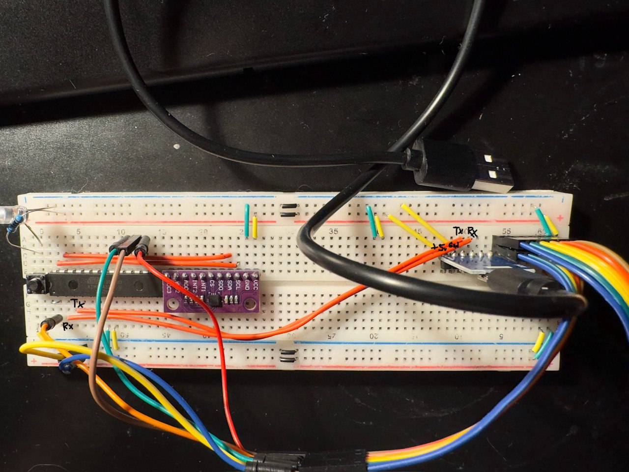
This is how I made the hardware: enter image description here

UPD

Tested on higher baud rate of 9600, it either gets stuck on even the very first print or starts spamming testing text (however the code waits for user to press any key). When it spams, texts are delimited with unknown character and the UART doesn't get stuck

UPD2 The problem is definitely not in terminal software (I'm using putty). Tested via WSL and GNU screen utility, the behavior is the same

\$\endgroup\$
6
  • 2
    \$\begingroup\$ You don't show how the modules arw connected, powered, etc. As the USB-UART module itself drops connection, this may be a hardware thing and nothing to do with software. \$\endgroup\$
    – Justme
    Commented Jun 1 at 13:55
  • \$\begingroup\$ If the UART implemented as a 16450, the interrupt handler needs to read the interrupt bit in the status register until it is inactive. This UART has a priority interrupt controller and you can get an interrupt (sometimes spurious) that maintains the device in interrupt mode. As the interrupt is edge triggered from the internal logic, if there is a pending interrupt (even spurious) it will never generate another interrupt to the host. This is not usually properly done in most drivers. I have seen this behaviour numerous times. \$\endgroup\$ Commented Jun 1 at 16:19
  • \$\begingroup\$ @Justme I've updated the question \$\endgroup\$
    – IC_
    Commented Jun 1 at 18:36
  • \$\begingroup\$ @PeterSmith I checked in the internet, it says it uses CP2102 chip \$\endgroup\$
    – IC_
    Commented Jun 1 at 18:37
  • \$\begingroup\$ the while statement is a candidate for lockups ... replace it with if ... add a counter to exit after a number of retries \$\endgroup\$
    – jsotola
    Commented Jun 1 at 19:09

2 Answers 2

0
\$\begingroup\$

There's no bypass caps anywhere and half of the innards of the ATmega328p is unpowered. There may be more problems but that's a good start fixing those already.

\$\endgroup\$
5
  • \$\begingroup\$ I didn't get it, what should I do? \$\endgroup\$
    – IC_
    Commented Jun 2 at 5:37
  • \$\begingroup\$ Tried to connect all unused pins together and to 10k resistor to ground, nothing happened. Those issues are still present. Also added a 1uF capacitor between VCC and GND \$\endgroup\$
    – IC_
    Commented Jun 2 at 10:53
  • \$\begingroup\$ Please link to the data sheet or schematics of that USB UART module, or any other documentation you used to make this circuit. Also, please understand that you are using internal oscillatot for AVR, and it has tolerance, which means it may tick at a frequency that makes the baud rate to almost on the edge of working and failing. \$\endgroup\$
    – Justme
    Commented Jun 2 at 11:57
  • \$\begingroup\$ I haven't found any datasheet about this module. I'll try to use external 8Mhz oscillator and check if it's better \$\endgroup\$
    – IC_
    Commented Jun 2 at 12:10
  • \$\begingroup\$ @IC_ If you have got no info on the module, you or anyone else cannot know how to use it correctly. \$\endgroup\$
    – Justme
    Commented Jun 2 at 13:04
0
\$\begingroup\$

I seemingly fixed the issue by adding 0.22uF electrolytic capacitor and 100pF ceramic. Bought a pretty low cost oscilloscope and it showed me voltage peaks ~7V on transmission lower and upper edges (+-0.4V due to low-cost oscilloscope precision).

          Atmega328p
 Rx                      Tx
  o                      o
  |                      |
 ----------          ----------
|          |        |          |
+          |        +          |
= 0.22uF   = 100pF  = 0.22uF   = 100pF
-          |        -          |
|          |        |          |
---------------|---------------
              GND

This seeminlgy prevented +7V spikes and UART module to spam/stuck (at least I didn't notice any bizarre behavior with this circuitry)

\$\endgroup\$

Your Answer

By clicking “Post Your Answer”, you agree to our terms of service and acknowledge you have read our privacy policy.

Not the answer you're looking for? Browse other questions tagged or ask your own question.