1
\$\begingroup\$

I simulated a circuit using LTspice, as shown in the image I attached. I applied a variable signal to the cathode terminal of a Schottky diode. I observed the same signal (with a Vf difference) at the anode terminal.

Can you explain why this happens? Normally, shouldn't these diodes not transfer the voltage at the cathode to the anode when reverse-biased? Here are the parameters for the cathode voltage:
Vinit: 0, Von: 5, Tdelay: 10n, Trise: 1n, Tfall: 1n, Ton: 10n, Tperiod: 200n.

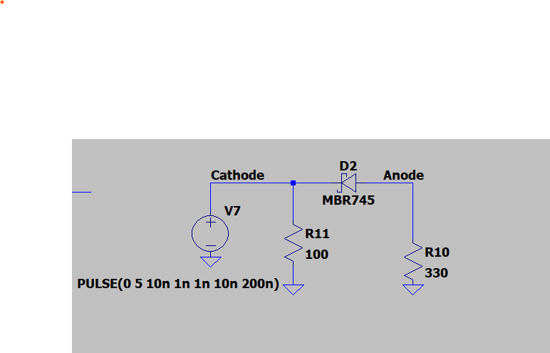
Simulation circuit

anode cathode voltage

\$\endgroup\$
1
  • 1
    \$\begingroup\$ 10ns pulse? your diode plays a capacitor. \$\endgroup\$
    – fraxinus
    Commented Jun 9 at 20:59

2 Answers 2

2
\$\begingroup\$

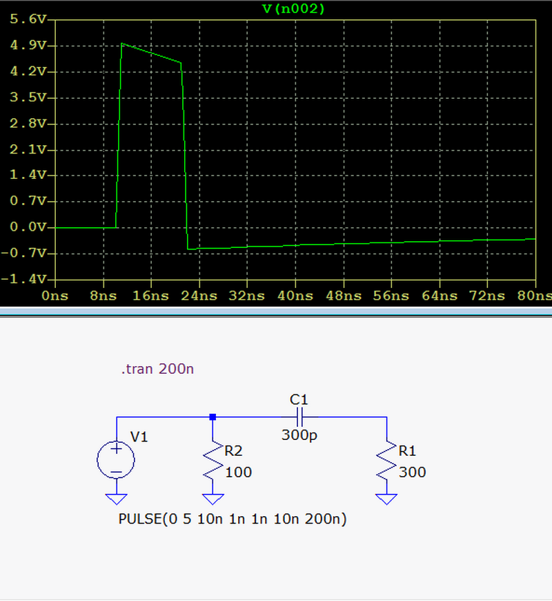
Schottky diodes tend to have high junction capacitance. For the MBR745 at 5 V reverse voltage it's around 300 pF.

Try it with something like a 1N4148 and you'll see a difference, there will be spikes as the pulse turns on and off due to the diode's capacitance, but not as much as with the Schottky.

Increasing the pulse time you can see the charge and discharge of the capacitance better, it will charge to the pulse voltage and then start to drop off. Replacing the diode with a 300 pF capacitor will give you pretty much the same waveform.

enter image description here

\$\endgroup\$
1
\$\begingroup\$

Diodes have a small, but not negligible, parasitic capacitance. That's what you're seeing here; the handful of picofarads of capacitance is enough to let such a short pulse through.

This capacitance actually depends strongly on the reverse bias voltage, with higher bias corresponding to lower capacitance. This is used to adjust the tuned circuit in digitally-controlled RF tuners, in lieu of the old-style mechanically-variable capacitor.

\$\endgroup\$

Your Answer

By clicking “Post Your Answer”, you agree to our terms of service and acknowledge you have read our privacy policy.

Not the answer you're looking for? Browse other questions tagged or ask your own question.