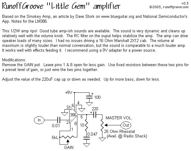
Here is an image of an amplifier circuit.
How can I modify this for a 10-50 times more gain. I put a wire from pin 1 to 8, but I didn't get enough gain.

Here is an image of an amplifier circuit.
How can I modify this for a 10-50 times more gain. I put a wire from pin 1 to 8, but I didn't get enough gain.

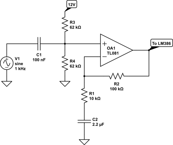
Leave pin 1 to 8 open. Add another gain stage ahead of the LM386.

simulate this circuit – Schematic created using CircuitLab
This non inverting amplifier has a gain of \$A=1+\dfrac{R_f}{R_i}\$. Gain can be increased by increasing the value of the feedback resistor. Add the LM386 gain stage and total gain becomes \$A=20(1+\dfrac{R_f}{R_i})\$.
The voltage divider and capacitor add a DC bias to the the non-inverting pin. This will allow it run from a single supply, and acts as a 50 Hz high pass filter. Do not forget to add C2 as well. Without it, the amplifier will just slam the positive rail.
However, if this is for that induction loop you keep talking about, I doubt you will ever be able to get enough power out of an LM386.
There is another way to set the gain, which the datasheet briefly mentions but it doesn't go into any detail.
"Gain control can also be done by capacitively coupling a resistor (or FET) from pin 1 to ground."
See:
http://www.wentztech.com/radio/resources/Technical-Info/_LM386/Unleash-lm386.pdf
which discusses how to use that method to get a gain of over 4500 (73dB). It requires careful layout and grounding.