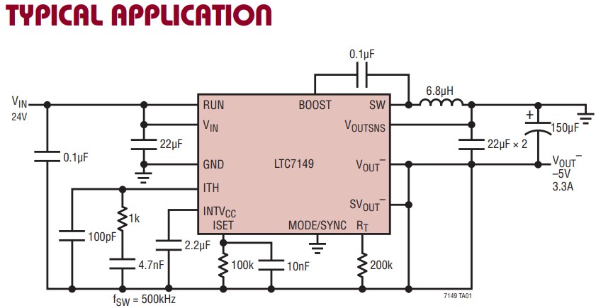
I'm looking at the data sheet for an Analog Devices LTC7149 step-down regulator. On the first page there's a "Typical application" circuit diagram that shows a capacitor on the VOUT- output that's labelled "22µF × 2".
Does this mean that the circuit should contain two 22 µF capacitors (presumably in parallel), and not just the one that is shown on the drawing?
- Why are there two capacitors? Perhaps because 44 µF isn't a common value, so 2× 22 µF in parallel provides this?
- Why not just draw two capacitors on the diagram? My guess is that it's simply to save space, as the figure is quite busy.

