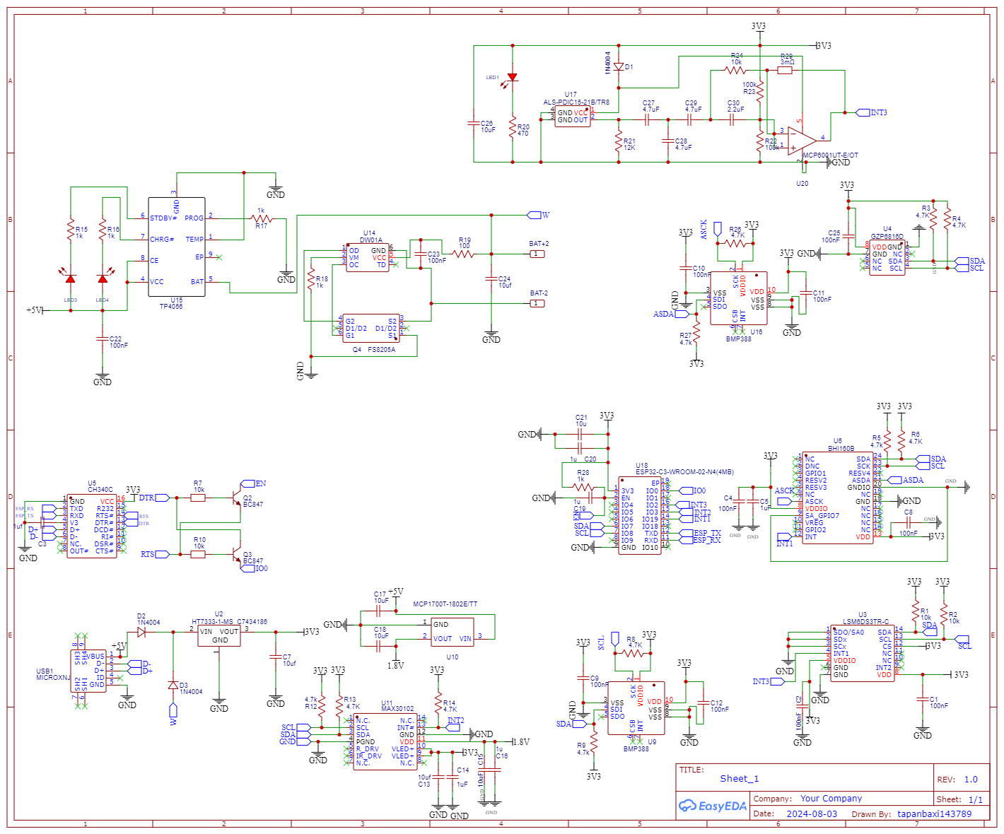
i'm very new at PCB designing and wanted to test out some smd sensors I have bought so I have designed this schematic. mainly I want a esp32 based board that can run on battery with sensors. I've used datasheets, google images and what not for reference my first PCB failed and this is my second version so I want to ensure that I'm on the right path and not order another pcb that won't work eventually. Also if anyone can confirm if I need a reset and boot switch for uploading code
-
\$\begingroup\$ We can't know what this thing is supposed to do or how it should function, so we can't know if it does what you want. We also don't know how this compares to your previous board, what was wrong with it and how you fixed it to assess if it now works better in that regard. Schematic review requests are difficult and open-ended as questions. \$\endgroup\$– JustmeCommented Oct 2 at 20:06
-
\$\begingroup\$ A better schematic may improve the response your question is getting, check this guide to draw better schematics: electronics.stackexchange.com/questions/28251/… \$\endgroup\$– Hans mitm FlammenwerferCommented Oct 2 at 20:25
-
\$\begingroup\$ Unnecessary use of node labels to make electrical connections are making this harder to analyse. Scattering of circuit sub-parts seems random (another reason to redraw and learn by those mistakes). \$\endgroup\$– Andy akaCommented Oct 2 at 20:41
-
\$\begingroup\$ You have an extra dot at U20 pin 3 that is shorting its inputs together. And what's that component in the feedback - a 3 milliohm resistor? You mean 3 megohms? Neither of those values are great choices. \$\endgroup\$– td127Commented Oct 3 at 1:06
1 Answer
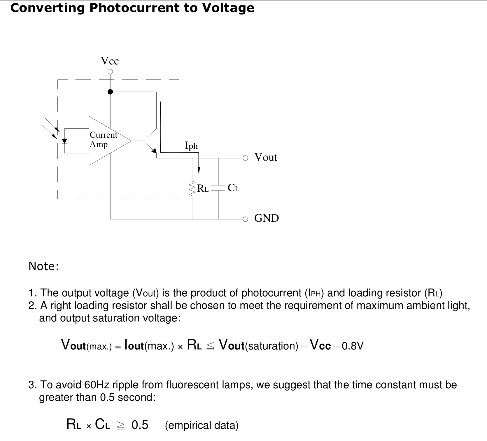
Your optical sensor , U17 compresses 4 decades of light from 1 to 1000 Lux into three decades of current which then gets converted to voltage from the follower into your selected load resistor. But your signal conditioner looks convoluted and is AC coupled. I don’t know the reason for this. The recommended circuit is below.
FWIW Vishay makes a Sharp design that spans 0 to 140 klux with an I2C output you may want to include, in a similar size SMD.
https://www.vishay.com/docs/84366/veml6030.pdf
I found your schematic easy to read, but I did not try to verify the functions.

