3
\$\begingroup\$

I am trying to learn about resonance in AC circuits and, in reading about them, one thing that made sense to me was the concept of a tank circuit. One should be able to input little bits of energy into a tank (or "resonant") circuit, and see this built up into something more, pendulum-sty le.

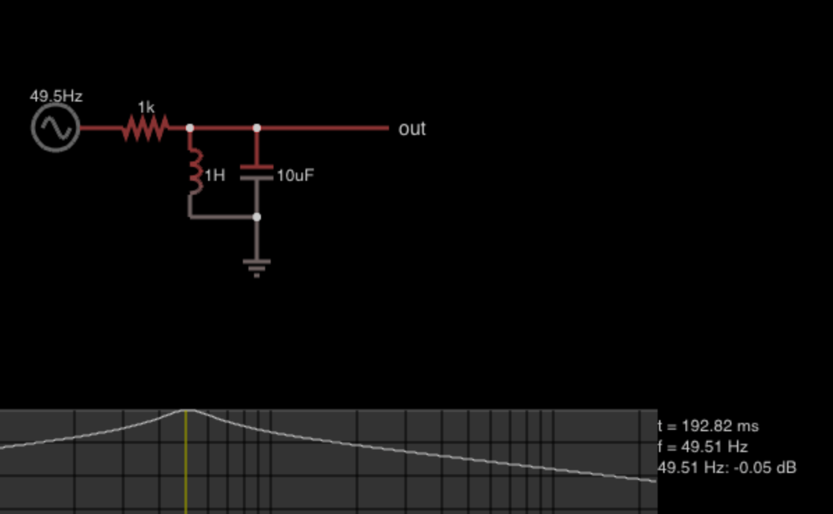
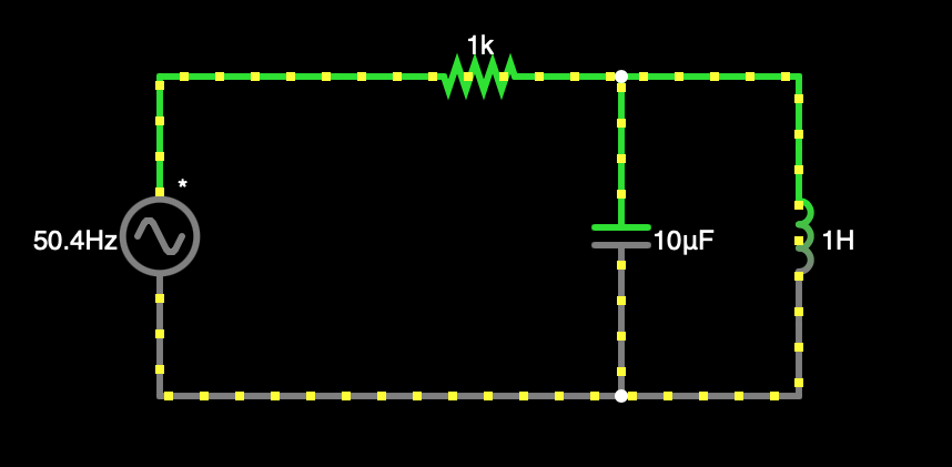
For example, the ARRL Extra Class License Manual says "[F]or resonant circuits such as tuning networks for amplifiers... internal voltages and currents can become high enough to arc across tuning capacitors or melt soldered connections, even at modest power levels." I wanted to observe this phenomenon in action. So, I made this in Falstad:

enter image description here

Sure enough, when I begin simulation of this circuit, current flow outside the tank circuit gradually zeroes, while current flow within the tank circuit builds to a crescendo. However, I have not found any way to insert a voltmeter or ammeter into this circuit and observe any numbers that reflect the claims in the ARRL Extra Class License Manual.

What am I misunderstanding here? Where can I observe these large voltages and currents that come with a resonant circuit?

\$\endgroup\$

3 Answers 3

4
\$\begingroup\$

Where can I observe these large voltages and currents that come with a resonant circuit?
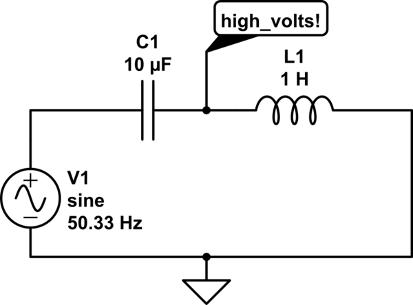
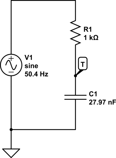
That 1k resistor is a problem. If you want to see large AC voltage, try simulating this version:

schematic

simulate this circuit – Schematic created using CircuitLab

At the resonant frequency of C1,L1 a huge AC current flows around the loop, since no resistance impedes its flow.

  • Frequencies below resonance cause less current, because C1's impedance is larger than L1's impedance.
  • Frequencies above resonance cause less current because L1's impedance is larger than C1's impedance.
  • At resonance, C1's impedance is exactly countered by L1's impedance since they have opposite sign, with a net sum of zero ohms.

It may actually be difficult to set V1's frequency to resonance, since with no resistance, it is very sharp (resonance is very narrow). Only at resonance will you get high AC voltage at the junction of C1,L1. With no resistance, AC voltage will ramp up continually.
If you try to build this, you cannot avoid resistance...V1 may have a small source resistance. L1 has resistance of the wire windings. C1 has some small series resistance too.


Edit
Simulating LC resonators where series resistance approaches zero, or where parallel resistance approaches infinite (in a parallel LC circuit fed by a current source) is fraught with trouble.
Some simulators by default add a tiny hidden series resistor to an inductor, so that a satisfactory circuit solution can be found. Otherwise, a "convergence error" might be thrown. Current sources might also add a hidden parallel resistance to avoid the same convergence problem.
On top of that, a transient simulation proceeds by stepping time in small increments, which doesn't properly simulate real-life.

The net result is that sharp resonance where resistance is far from reactive impedance can result in improper simulation results - proceed with caution.
For most simulators of realistic components having internal losses, you should get reasonably accurate results, but it is always good to do a sanity-check.

\$\endgroup\$
3
  • \$\begingroup\$ If you connect that the grid, which part explodes first. Or did you intend to emulate an Op Amp voltage source? \$\endgroup\$
    – D.A.S.
    Commented Oct 26 at 0:29
  • \$\begingroup\$ The context of OP's question pointed to a simulation, not a real-life attempt (I hope)! I actually did this experiment to see how much AC amplitude I could get from a standard bench function generator with 20V pk-pk output voltage and 50 ohm output resistance. At resonance, got something over 400 V p-p at resonance...the function generator's internal 50 ohms limited current into the resonator. I decided not to stress my 'scope probe further. You have to work hard to build LC resonators having Q over 1000. \$\endgroup\$
    – glen_geek
    Commented Oct 26 at 1:47
  • \$\begingroup\$ Yes Q= 20 gain is pretty easy , 100 is a practical limit and 1000 requires a keen understanding of L/R ratio effects on C and more gets one into MEMs and Xtals \$\endgroup\$
    – D.A.S.
    Commented Oct 26 at 2:35
2
\$\begingroup\$

It's better to think of the LC network as an impedance converter.

This becomes more explicit when studying transmission lines (TLs), where we may call a λ/4 stub an impedance transformer, effectively inverting the impedance with respect to its characteristic impedance. TLs are an advanced topic, but there exists an equivalence between them (when used for narrow-band purposes such as this) and RLC lumped-equivalent circuits, so, without stating what that equivalence is or otherwise applying it, merely understand that there is a deeper connection across AC steady-state and wave mechanics.

It also simply works in and of itself, as the L-match network.

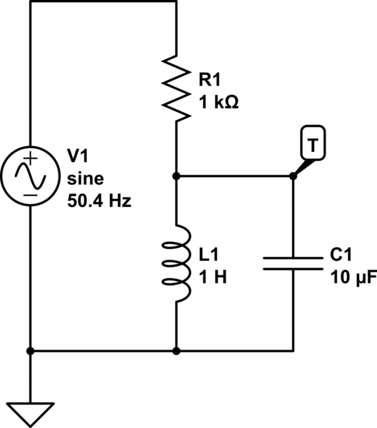
We can redraw your circuit by canceling out the admittances: YC = j3.1667mS, YL = -j3.1578mS. (Admittance is the reciprocal of complex impedance: \$Y = G + jB = \frac{1}{Z} = \frac{1}{R + jX}\$.) These add in parallel, leaving j8.8µS, and importantly, no [real] conductance; these are ideal L and C.

The circuit reduces to an impedance divider:

schematic

simulate this circuit – Schematic created using CircuitLab

which as you can see amounts to about no loading at all, so the current through the source and resistor is tiny, and the "output" voltage essentially equal to the input voltage.

This circuit cannot have voltage gain; at resonance, it is a resistance divider, with the gain ratio given by the ratio of resistances: the total effective loss in L and C.

But viewing it as an impedance converter, consider the current through the capacitor:

schematic

simulate this circuit

we have V(T) = 1V, and IC = 3.167mA (at a phase of 90°; check the simulation, Frequency Domain Simulation). We have voltage and current, and their ratio here gives an impedance, \$Z_0 = \sqrt{\frac{L}{C}}\$ or 315.77Ω. Sound familiar? :)

In particular, notice that the short-circuit current through R1 is at most 1mA. Yet 3mA is flowing below it! Your resonant gain is not in terms of voltage here, but in terms of the converted quantity: current.

\$\endgroup\$
2
\$\begingroup\$

TL;DR You need a current source with high R shunt load to amplify V at resonance in a parallel tank. Otherwise you need a low loop resistance with a series LC to amplify voltage between LC.

Zo = sqrt(L/C) = 316 Ohms fo = 1/(2pi*sqrt(LC)) = 50 Hz Qp = Rp/Zo=1k/316= 3 for parallel using ideal reactors unity gain.

Since the parallel tank is open circuit at resonance there is no current thru the resistor and the output is unity gain. You need a current source to get voltage gain.

A series LC resonator has impedances which are equal but opposite polarity so it cancels out to zero Ohms reactance limited mainly by the L winding resistance.

Qs = Zo/Rs with a low series R from all cmponents, DCR, ESR and voltage source.

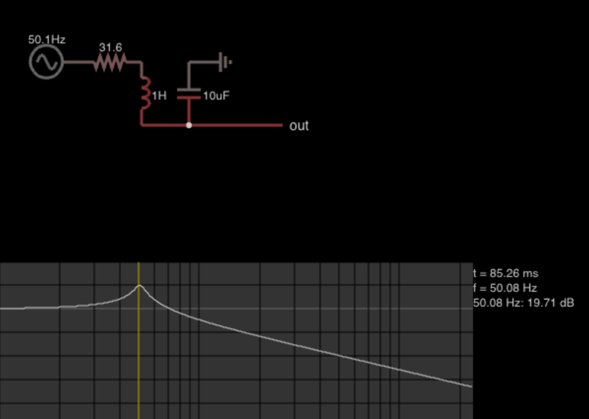
If the resonant Zo is very low (<<1 kohms) that is the characteristic of a high Q series RLC. A resonator is possible due to a high 2pifL/(DCR +Rs) ratio but only if Rs is near zero. enter image description here

A DC relay coil is usually over 1H but DCR depends on V/I rating might be a practical experiment following the above guidelines. But you could get a Q = 100 voltage gain between L & C using a buffered OpAmp in the milliohm range. Choose a low Vdc for safety like +/-5V. Then find a low voltage DC relay and measure DCR and L and tune C with a non-polar film cap for microwave ovens. Then you might generate Q=10 times 10V with a tuneable frequency. enter image description here With voltages in the 1kV range learn how not to shock yourself or blow up epoxy caps before you try this. That puff of smoke might be carcinogenic.

\$\endgroup\$

Your Answer

By clicking “Post Your Answer”, you agree to our terms of service and acknowledge you have read our privacy policy.

Not the answer you're looking for? Browse other questions tagged or ask your own question.