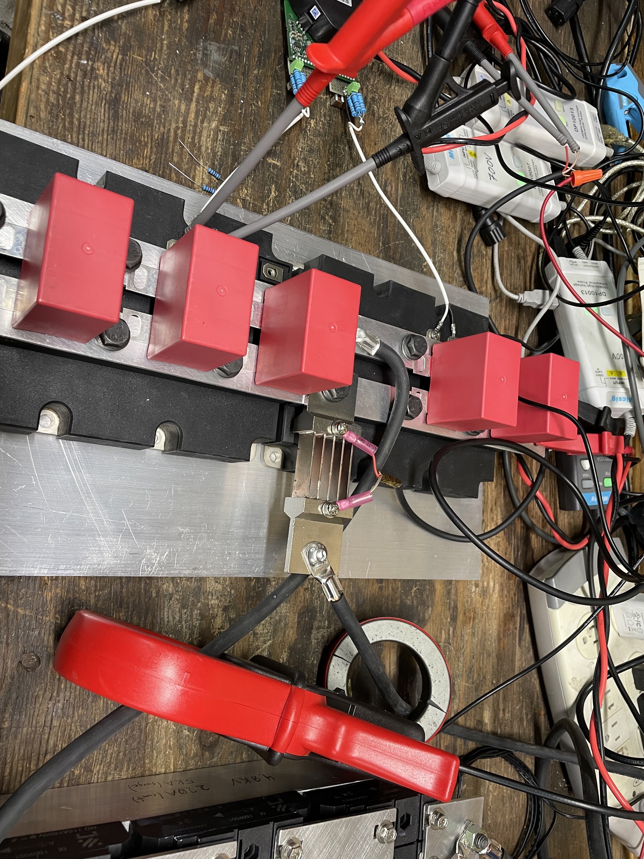
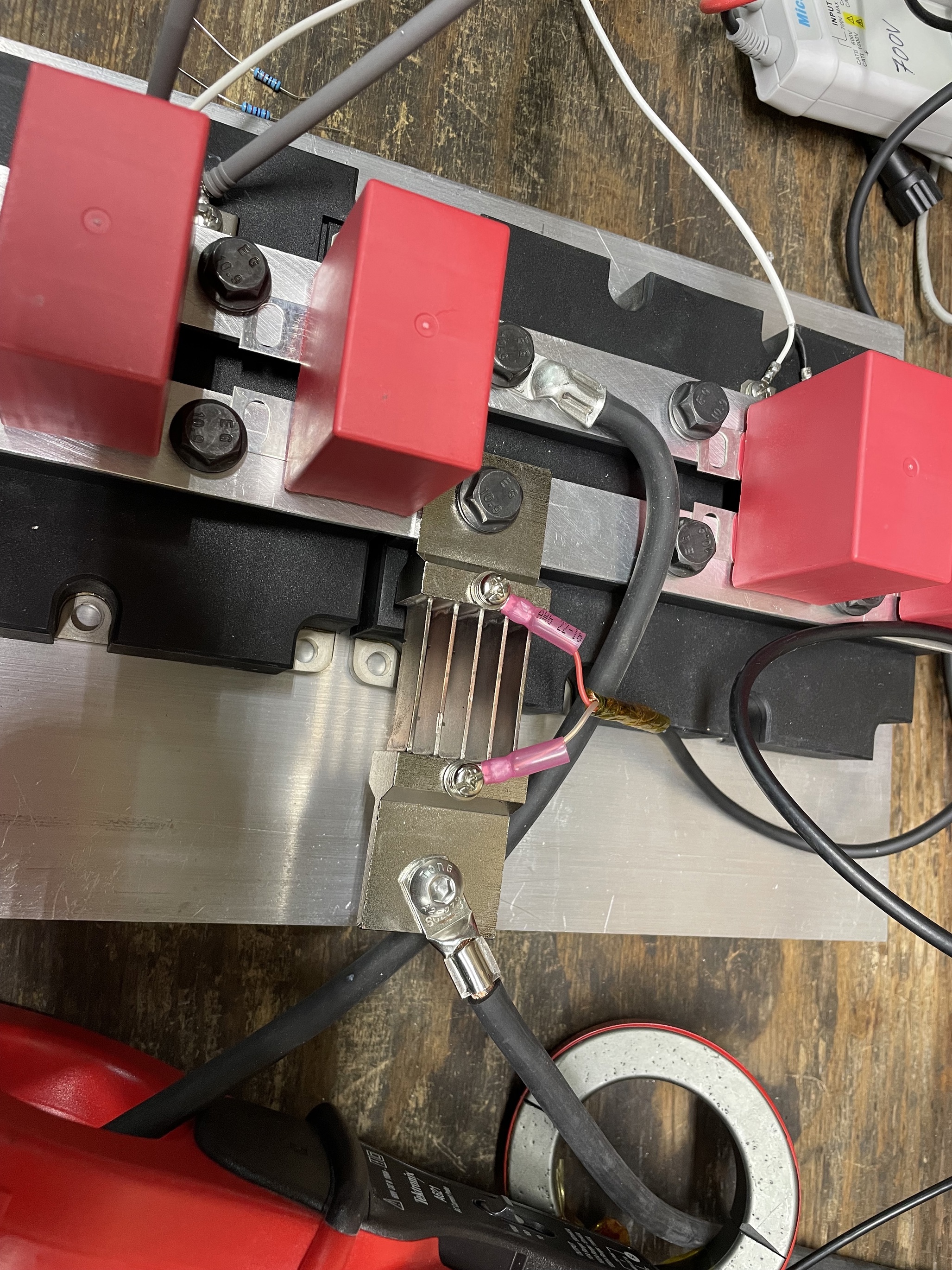
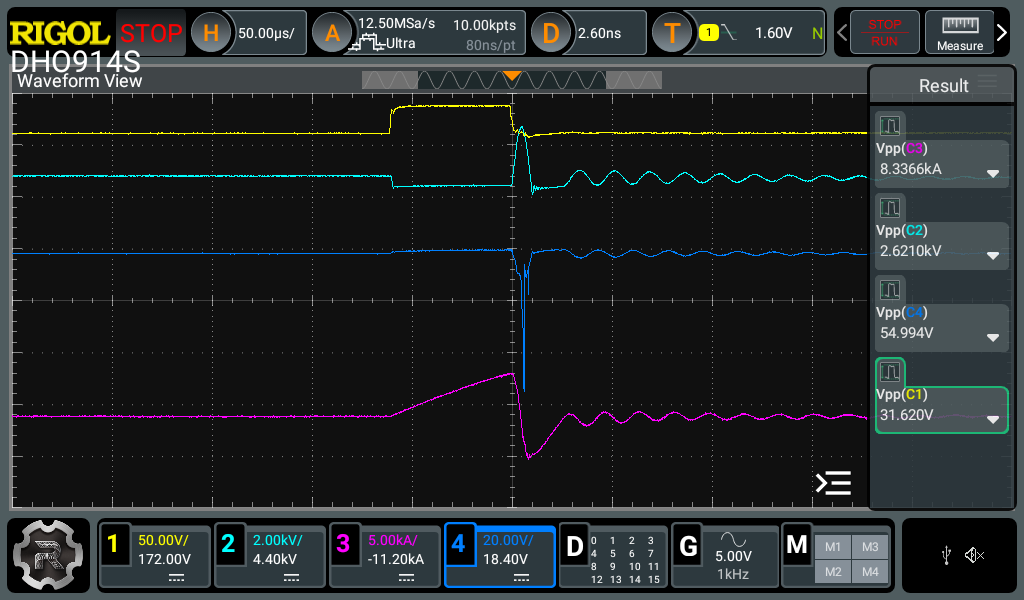
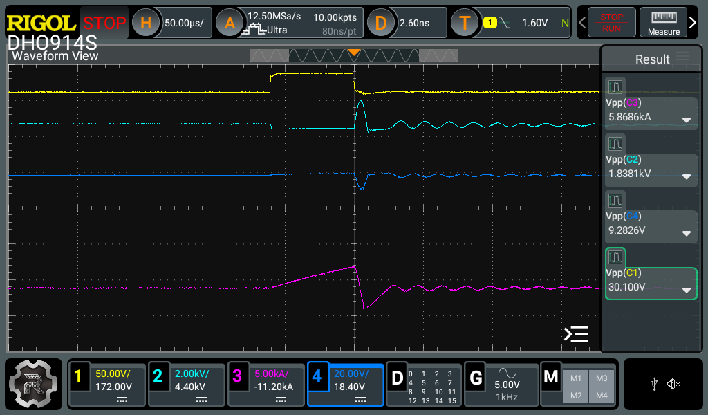
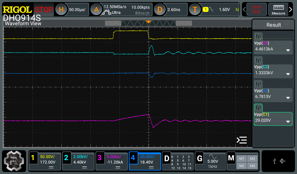
I'm trying to measure the peak current of a pulse generator, I've been using a current-transformer type current probe (TEKTRONIX A621 AC) which can only measure up to 2000amps. I've also tried a few shunt resistors (500A, and 1500A continuous rated. The measurements included below are measuring the 500A shunt. The measurements I'm getting on the shunt are not what I'm expecting (they don't match the signal of the tek current clamp). The signal looks like inverted voltage across the IGBT (light-blue trace), and above about 8kA (measured from the tek current clamp(which is only rated for 2kA, it shows a very strange spike which is confusing me. Am I missing any filtering or anything here for the shunt mesurement? Should it match the trace of the tek current clamp? Thank you all for any help/advice as always!
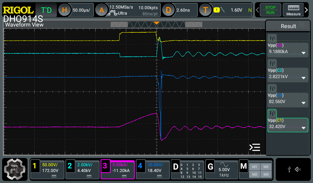
Here are some traces showing the various signals at ~9kA, 8kA, 6kA and 4kA.
Ch1(Yellow) = IGBT gate signal
Ch2(Light-Blue) = voltage across the IGBT
Ch3(Magenta) = Current measured from Tektronix current clamp)
Ch4(Dark-Blue) = Voltage across shunt resistor
Below I've included a few photos of the setup of the current shunt and the setup. I've switched to using shielded wire from the shunt to the differential probe leads.
