5
\$\begingroup\$

I want two atmega32s to communicate over a range of 1000ft, so I decided to use a serial wire for it. I know rs232 is not a good way to communicate over this large range, so I decided to use RS485 which is a balanced pair. For this I want to use MAX485 chips like these.
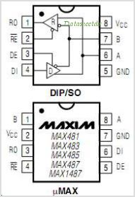
MAX485 Chip diagram

Now I wrote all the code to use it and got it working for short wire communication with a battery powering my ATmegas (and the MAX485 chips) (I cannot produce the code here as it is for a company where I am just an intern, but as it works in short wire the code is not the problem). What the program basically does is, one atmega sends "Paresh" on serial, the other atmega receives it, does a strcmp if it is indeed recieved as "Paresh" it sends out "Mathur". If the first atmega receives "Mathur" it again sends paresh and the cycle continues.

All this works just fine for serial mode, short wire and on a 6V battery. But as soon as I switch to a CAT-5 cable I get packet loss. I printed what ever one receives on an LCD and after a few cycles (and sometimes even for the first transfer) there is strange strings received. The problems are:

  1. It works for short wire but not a 30ft CAT-5 cable
  2. It works for 6V battery but not for 12 volt battery or a 12V adapter.
  3. It works for normal serial wire upto 10ft but not more than that.

The things I have tried are:

  1. Added capacitors to fade out any ripples in the supply. (470uf caps).
  2. Increased delays between switching from transmit to receive modes ( _delay_ms(3); ).
  3. added caps to the supply to the modules.
  4. Adding 120ohm terminal resistance to both modules.

What should I do? Please do no suggest any alternatives to the the thing, it would hurt the hacker in me. Why cannot I use an RS485 communication for exactly the purpose it was designed .i.e long distance communication over serial.

Update 1: I used 120ohm terminal resistance. Update 2: I am on a 9600 baudrate.

\$\endgroup\$
11
  • \$\begingroup\$ What's the baud rate? When you say it works for a 6V battery but not 12V, you are using a regulator down to 5V, right? Can you use an oscilloscope to look at the waveforms? \$\endgroup\$
    – W5VO
    Commented Dec 19, 2010 at 17:56
  • \$\begingroup\$ I am using a 5v regulator, the input to the regulator varies. No I do not have an oscilloscope at hand. The baud rate is 9600 \$\endgroup\$
    – Rick_2047
    Commented Dec 19, 2010 at 18:00
  • 1
    \$\begingroup\$ @Rick_2047, Time to needle the boss for an o'scope! It really helps to be able to send UUUU... and verify baud-rate, slew-rate, ringing, etc. \$\endgroup\$
    – tyblu
    Commented Dec 19, 2010 at 18:43
  • 1
    \$\begingroup\$ @tyblu, do you know the funny thing? we also manufacture an oscilloscope for kids. It hurts I know. \$\endgroup\$
    – Rick_2047
    Commented Dec 19, 2010 at 18:46
  • 1
    \$\begingroup\$ The trick is in the timing of switching between transmit and receive modes. This solved the problem when we also added a large capacitance between ground and power. But my advice would be to abandon this IC is possible, its just a mean IC. \$\endgroup\$
    – Rick_2047
    Commented Jan 30, 2011 at 17:48

3 Answers 3

4
\$\begingroup\$

In my [in]experience, 99% of serial communication errors are due to timing mismatches; the other* 99% is due to wiring hoopla.


  • It works for short wire but not a 30ft CAT-5 cable
  • It works for normal serial wire upto 10ft but not more than that.

CAT-5 cable is twisted pair (also, all of what I have used is also shielded, but apparently this is not common); I assume the "normal serial wire" is two loose wires. As wiring gets longer, your nice digital rise times stretch out, effectively shrinking the available window for sampling incoming data. Twisted pair helps this a bit. What this really means is that your UART clock must be prescaled more accurately to the baud rate being used. System clocks for perfect USART communications should be multiples of 1.8432MHz. Short-range communications can tolerate a few percentage error, but as your sampling window shrinks it must be more accurate. What your prescaler (int), and baud error?

prescaler = (int)(F_CPU / (USART_baudrate * 16) - 1)
actual_baudrate = F_CPU / (prescaler * 16)
baud_error = 100% * (1 - actual_baudrate / USART_baudrate)

  • It works for 6V battery but not for 12 volt battery or a 12V adapter.

This sounds fishy! This may be a completely different problem, perhaps causing your widget to reset due to a dirty supply or poor regulation. There are stability issues with LDO linear regulators and varying capacitive loads; there may be dissipation issues from a 12V supply; if one isn't using a LDO regulator, then a 6V battery will really be giving you 4.5V to 5V, and won't be well regulated. Power supply issues are in a class all their own, and must be rectified before peripherals can be effectively debugged.

Other than this, there is always the issue with environmental interference, or EMI. RS-485 is made for this, but should be used with twisted pair[, shielded wire,] like the CAT-5 cable you've used.

**(What, my math is wrong? Do you know who I am!? ;)*

\$\endgroup\$
5
  • \$\begingroup\$ Wow this is nice, (I heard from the other developer who is working the graveyard shift that the problem is solved with more delays inserted). BTW my prescale was 256 and 1024 (tested both) on a 7.something something type xtal (don't remember the exact number). \$\endgroup\$
    – Rick_2047
    Commented Dec 19, 2010 at 18:43
  • \$\begingroup\$ A newbie comment, but how do we know that CAT5 cable is shielded? \$\endgroup\$
    – AndrejaKo
    Commented Dec 19, 2010 at 18:44
  • \$\begingroup\$ @AndrejaKo, to tell you the truth, I just assumed it all was, since any 5e cable I've stripped has had the sheath - but now I see that you can get unshielded CAT5. 'Suppose you had best simply check! \$\endgroup\$
    – tyblu
    Commented Dec 19, 2010 at 18:51
  • \$\begingroup\$ OK. Thank you for clarifying that. I thought that there could be some other way to remotely identify if cable is shielded or not. \$\endgroup\$
    – AndrejaKo
    Commented Dec 19, 2010 at 18:53
  • 1
    \$\begingroup\$ @And: the cable should say "STP" on it, instead of "UTP" \$\endgroup\$
    – Nick T
    Commented Dec 22, 2010 at 5:22
3
\$\begingroup\$

One thing that you haven't mentioned is using termination resistors. RS485 needs termination resistors at each point of the bus, usually 120 ohms.

Check out this document published by Maxim on RS485 wiring.

\$\endgroup\$
1
  • \$\begingroup\$ Ah, I forgot, I did use 120ohm terminal resistance. \$\endgroup\$
    – Rick_2047
    Commented Dec 19, 2010 at 17:49
2
\$\begingroup\$

I'm currently working on a maglock door security system, and am using these same chips to transmit data from the RFID reader to an Arduino about 200ft away. I as well have had all kinds of problems with these annoying, but awesome :), chips. I'm not sure I'm operating at 100% fool-proof yet, but here's a few things I've found out:

• There's a tradeoff between transfer rate and susceptibility to EMI. The MAX485 has a high transfer rate, but is very influenced by EMI. Try the MAX483. Same chip with slower transfer rate, but very little EMI.

• In some cases, such as with a long cable distance, I've found it to work better without any terminating resistor...don't ask me why. :)

• Make sure both DE and RE pins are connected to either ground or +5V. They aren't required to be connected depending on whether you're in transmit or receive mode, but I could swear I've had better results when neither of them are left floating.

\$\endgroup\$
1

Your Answer

By clicking “Post Your Answer”, you agree to our terms of service and acknowledge you have read our privacy policy.

Not the answer you're looking for? Browse other questions tagged or ask your own question.