1
\$\begingroup\$

I have a Mechanical Engineering Master Thesis about positioning control of a pneumatic system with Model Predictive Control. I am primarily an electrical engineer and i do not know much about electronics. I need to design an interface card in order to connect a valve (5/3 way), two pressure sensors, a linear scale to my NI-PCI-6010 data acquisition card.

I have a bunch of questions about them. I tried to find solutions about them but none of them is enough for me. I wish you can help me.

However proportional valve (http://xdki.festo.com/xdki/data/doc_ENGB/PDF/EN/MPYE_EN.PDF) needs to be driven with 4-20 mA, my PCI-6010 card (http://www.ni.com/pdf/manuals/371498a.pdf) doesn't support it as i understand. Its analog output have a range of -5 to +5 V, i need to convert it into 4-20 mA.

First of all, do I need to convert -+5V or can I use 0-5V instead? I have seen lots of voltage-to-current converters in other websites, but all of them is about converting 1-5 V to 4-20 mA, I think there is an offset problem for 0-5V. I have found a non-inverting summing amplifier that can do what I want, but when input voltage reaches 5V, output current reaches 20,496 mA and this is surely a problem, also i need linearity.

I have found an IC that can convert 0-5 V to 4-20 mA (XTR110, I think you all have a word to say about it), but I cannot wait to purchase it, because i couldn't find any distributor in my country. So that I want to design a PCB in order to get over this problem.

Also I don't want to use a passive voltage-to-current converter. Here is the circuit I designed.

0-5 V to 4-20 mA Converter

V1 = 5 V, Vref = 1 V (for offset problem)

Also; when V1 = 0V, output current is 4,037 mA. But it is not a big problem. Other values are;

V1=1 V, Iout=7,329 mA

V1=2 V, Iout=10,62 mA

V1=2.5 V, Iout=12,267 mA

V1=3 V, Iout=13,912 mA

V1=4 V, Iout=17,204 mA

As you see, I cannot achieve a setpoint value for my valve too (It needs 12 mA for middle position).

Of course I don't want you to do my thesis for me, but I stuck on early stage of my thesis and if I cannot found a solution about it I absolutely have a real bad time.

Thanks in advance.

\$\endgroup\$
4
  • 1
    \$\begingroup\$ Are you sure 267 microamperes is unacceptable tolerance? You can determine your exact positions empirically and use those as 'calibration factors' in your control software. \$\endgroup\$
    – HL-SDK
    Commented Sep 12, 2013 at 14:57
  • 3
    \$\begingroup\$ Out of curiosity, why don't you want a passive solution? A resistor is a voltage to current converter because of that whole V=IR thing. 250 ohms gives you 0-20mA for 0-5 V, real linear. \$\endgroup\$
    – Matt
    Commented Sep 12, 2013 at 14:57
  • \$\begingroup\$ Because the real load affects the current, output current depends on the voltage drop across the load. I must able to send the specific current, no change can be tolerated. Yes, it is unacceptable, because of using proportional valve, 0,267 mA means that first chamber will have an input and this effects my control signal. \$\endgroup\$ Commented Sep 12, 2013 at 15:02
  • 1
    \$\begingroup\$ For the purposes of experimentation, you can request free samples of the XTR110 from ti.com, if you have a company email address. On the same page, you will also see links for where to order the parts from, in your country. For some countries and certain products, TI also supports direct ordering from the site. Besides, you can buy single pieces from eBay.com for shipment directly to you. \$\endgroup\$ Commented Sep 12, 2013 at 15:40

3 Answers 3

1
\$\begingroup\$

I don't recommend you to use the design in the picture. OAs ( Operational Amplifier) are good for Voltage gain and High impedance output, but not to "play" with current, the current output is sensible with the components tolerance. Try to simulate your circuits with variation of 5% in your devices (resistors & VCC) and see the output. When you will buy the components they will have deviations about 1% to 5%, depend on the quality of the materials you will buy.

Transistors are the devices to play with current gains, but impedance could be the problem.

See also the tolerance for the Valve mid-position for current, it is 1.3%:

Voltage type [V DC] 5 (±0.1)
Current type [mA] 12 (±0.16)

Your are right the 12.267 mA are not correct ( max. acceptable would be 12.16 mA), take this into consideration because it means: the tolerance current output of your circuit must be max. 1.3%!!!.

It could means also that maybe temperature compensation of your output must be implemented depend on the range of temperature where the device will operate and ICs you will use.

I have seen the Page 6 Datasheet of the valve:

Setpoint value
Voltage type [V DC] 0 … 10
Current type [mA] 4 … 20

Why don't you try to control the valve with "Voltage type"? I think it is easier to transform your +-5V to a 0-10 Volt linear signal with mid-position on 5V. And you have a little more tolerance (2%) requirement for your output. It is easy, you can use an OA adder with a two inputs: one a +5V offset and the second your +-5V signal (you must check the tolerance).

\$\endgroup\$
1
  • \$\begingroup\$ Thank you so much for this answer, yes you are right. I did not think about resistor value deviations and temperature. There are two types of this valve, one of them uses voltage input and the other one uses current input. Unfortunately, i have the one that uses current input. \$\endgroup\$ Commented Sep 12, 2013 at 17:55
1
\$\begingroup\$

enter image description here

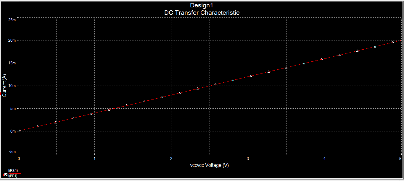
I think you should find this circuit useful. Here if you change R1 pot then for 1-5V voltage vary gives corresponding current in between 4-20mA. through the load resistance R3. The V vs I plot as shown in this below graph. enter image description here

\$\endgroup\$
0
\$\begingroup\$

So I have tried lots of circuits in order to achieve 4-20 mA linearly. I have designed a circuit with 3 TL081 operational amplifiers and succeed to a nearly perfect result. Here the circuit I have designed;

enter image description here

Only problem is when the input voltage is 0 V, output current is 3,98 mA which can be acceptable. If there is anything to improve -or I did wrong-, please tell me. I hope anyone who could not find anything about 0-5 V to 4-20 mA converter in Internet like me, can reach this circuit.

Thanks for your supports.

\$\endgroup\$
0

Your Answer

By clicking “Post Your Answer”, you agree to our terms of service and acknowledge you have read our privacy policy.

Not the answer you're looking for? Browse other questions tagged or ask your own question.