0
\$\begingroup\$

I'm rather confused by the behaviour of an LED here, I wonder if someone can get my head around it?

I have a microcontroller-based circuit @3.3V (using an LM2937 LDO regulator) driving a standard LED (2V ish voltage drop, 20mA If) via a digital output. So far so simple.

When I use my circuit simulator software...if I connect the LED directly to a 3.3V source, with no series resistor, it tells me it would draw 14mA ish. This is ok for the LED and my PIC I decide, and connect it up. Sure enough, when I do so, my ammeter tells me that 10-11mA flows through the LED. Great...no problem, I think to myself.

However, when I connect it to my bench DC power supply @3.3V, it displays ~100mA as the output current. A separate ammeter inline shows the same...a second ammeter agrees. However, the LED doesn't pop.

What's going on here?

\$\endgroup\$
3
  • \$\begingroup\$ What exactly are you asking? You describe several events so it's not clear what you mean when you ask "what's going on". \$\endgroup\$
    – Joe Hass
    Commented Feb 7, 2014 at 23:53
  • \$\begingroup\$ Why does the LED appear to draw 100mA when connected to the PSU, but 10mA when connected to the microcontroller at the same voltage? \$\endgroup\$
    – Jon
    Commented Feb 8, 2014 at 0:02
  • \$\begingroup\$ If the voltage drop of the LED is 2ish volts, and your supply is 3.3 volts, what do you think will happen to the other 1.3 volts? See How can I efficiently drive an LED? or Why do we need resistors in led or any of the thousands of other questions tagged led and current \$\endgroup\$
    – Phil Frost
    Commented Feb 8, 2014 at 3:47

2 Answers 2

7
\$\begingroup\$

A PIC output does not behave like a direct connection to a power supply.

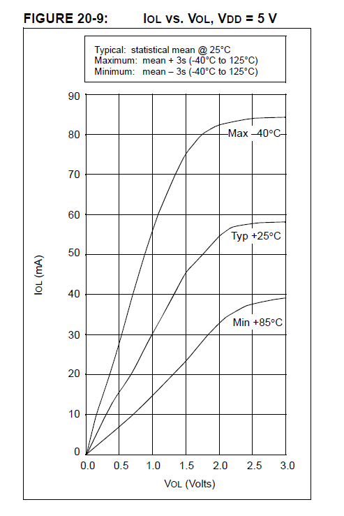
The output of a PIC operated from 3.3V would behave (roughly) something like a 30-150 ohm resistor, depending on a number of factors.

The shape will be similar to this (5V) but the numbers will likely be quite different:

enter image description here

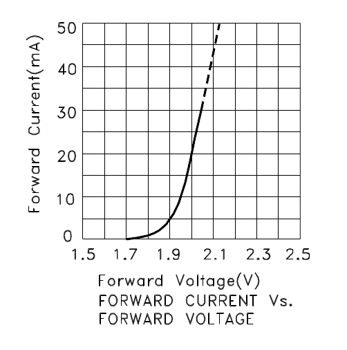
The LED has a voltage-current curve like this:-

enter image description here

As you can see, with 3.3V directly across the LED, the current will be very high (it will behave a bit differently off the graph).

100mA will damage most small LEDs fairly quickly. You'll also likely see the color change as the chip overheats (it will move in the direction of longer wavelength as the chip heats). The opposite of when you dip an LED in LN2.

On the other hand, when you connect it directly to an output, the output acts sort of like a current limiting resistor (though not a very predictable one), and it probably will not see a destructive current (not guaranteed).

Bottom line, if you want a predictable and safe current, you should use a current limiting element of some kind- a resistor is usually a reasonable choice.

\$\endgroup\$
2
  • \$\begingroup\$ Could you cite the sources for these figures, please? \$\endgroup\$
    – Joe Hass
    Commented Feb 8, 2014 at 2:18
  • \$\begingroup\$ @JoeHass Sure, Joe, links added. \$\endgroup\$ Commented Feb 8, 2014 at 2:55
3
\$\begingroup\$

The PIC won't be able to supply the current but the power supply will. Forget about simulating a LED on a supply and trust what the data sheet for LED says.

Because the PIC can't supply the current if you use your meter to look at the volts across the LED it will indicate 2 to 3 volts most probably, even though the supply is 3.3 volts.

\$\endgroup\$

Your Answer

By clicking “Post Your Answer”, you agree to our terms of service and acknowledge you have read our privacy policy.

Not the answer you're looking for? Browse other questions tagged or ask your own question.