For a while now I'm working on a project where I want to control 48 stepper motors.
A pair of two motors is controlled by an Atmega8. All modules are connected as slaves on an I2C/TWI-bus with an Arduino acting as the master device.
A while ago I already posted a question about power supply issues and got many useful comments regarding ground loops, capacitors and PCB design. The main issue that the Atmega8s are not working properly anymore when I run more than 5 of the motor-control-modules simultaneously.
I've tried to implement most of the suggestions, but still have some questions for possible improvements:
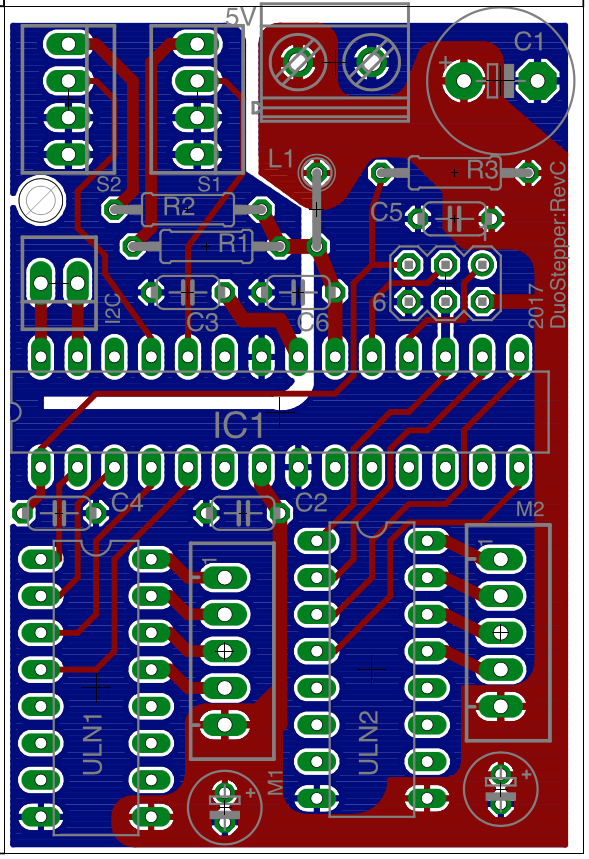
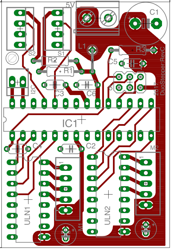
- Are the large capacitors at the VCC-input as well as next to the motors placed properly?
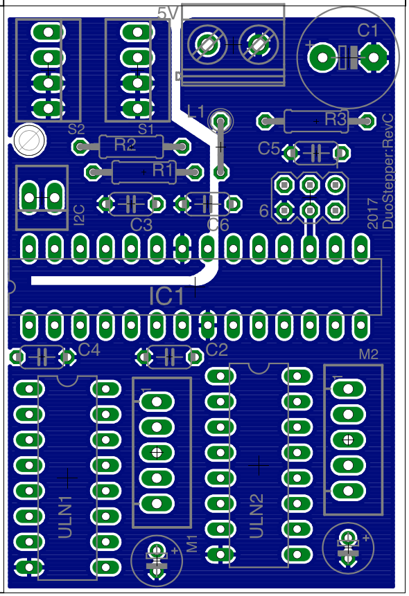
- Is the layout of the "power-plane" designed properly?
- Is the decoupling of the analogue ground any good?
One module with both steppers running takes up roughly 0.5A at the same time. My power supply should be capably of running all modules at the same time. I'm running a star-topography with thick wires between all modules.
Okay, so here is what the whole thing looks like (I2C-bus/resistors not displayed to keep it simple):
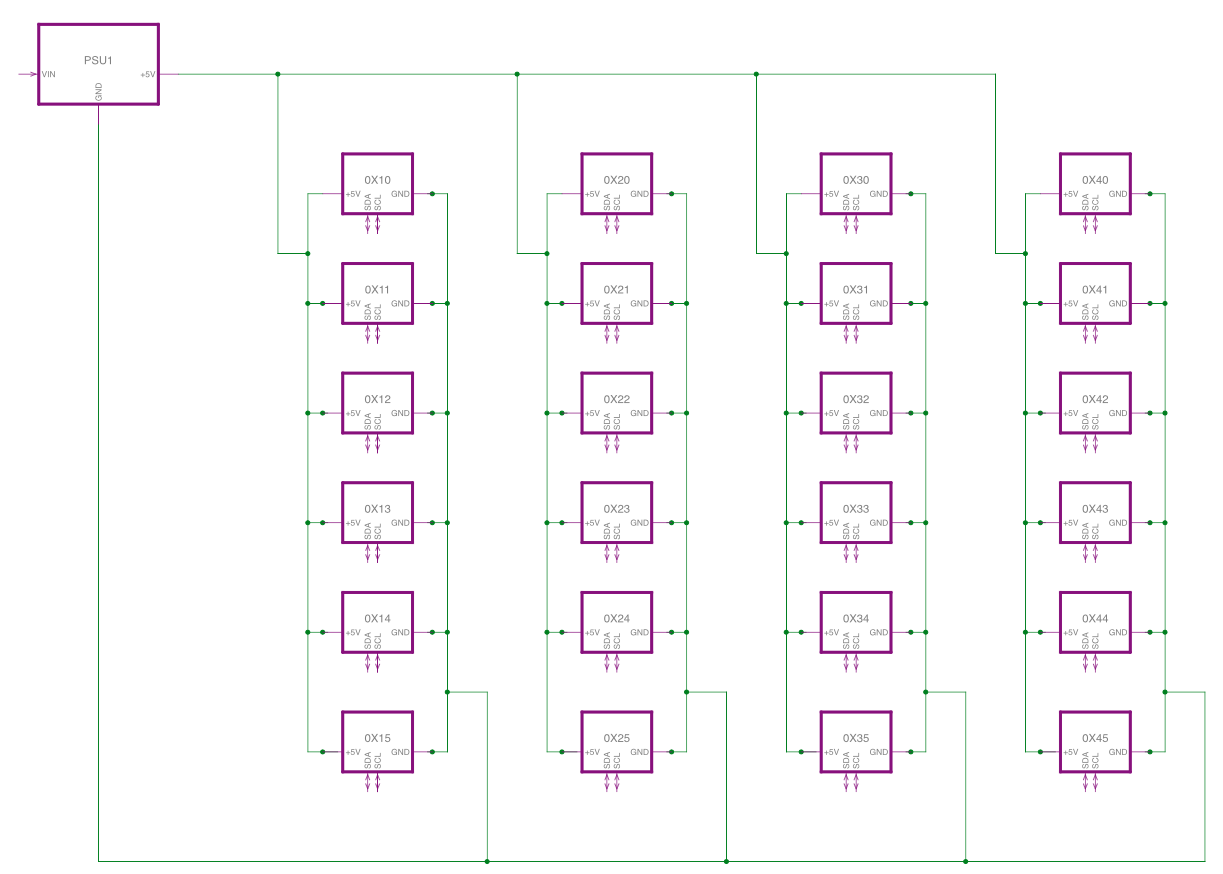
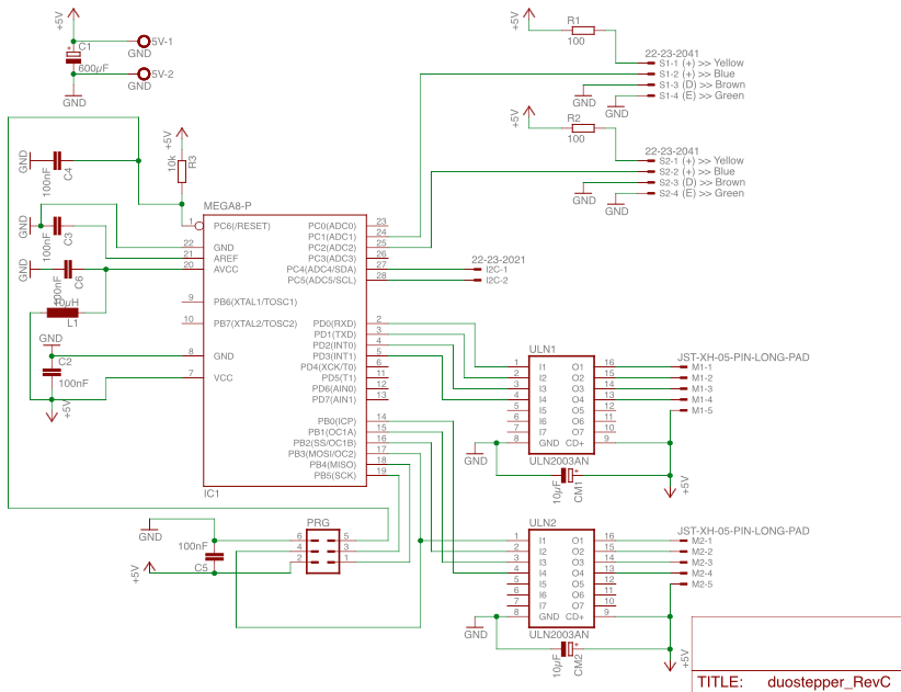
The circuit for each of the modules (0X10 etc.) is looking like this. Some notes about the different sections:
- The two motors on the bottom right are connected to the ports PB and PD via darlington arrays
- Connected to PC1/PC2 on the top right are two optical sensors for homing the stepper motors
- PRG on the bottom is the programming port for the Atmega8
The PCB design (40 x 60 mm) I plan to order looks like this. This is not implemented, yet!
