2
\$\begingroup\$

For a while now I'm working on a project where I want to control 48 stepper motors.

A pair of two motors is controlled by an Atmega8. All modules are connected as slaves on an I2C/TWI-bus with an Arduino acting as the master device.

A while ago I already posted a question about power supply issues and got many useful comments regarding ground loops, capacitors and PCB design. The main issue that the Atmega8s are not working properly anymore when I run more than 5 of the motor-control-modules simultaneously.

I've tried to implement most of the suggestions, but still have some questions for possible improvements:

  • Are the large capacitors at the VCC-input as well as next to the motors placed properly?
  • Is the layout of the "power-plane" designed properly?
  • Is the decoupling of the analogue ground any good?

One module with both steppers running takes up roughly 0.5A at the same time. My power supply should be capably of running all modules at the same time. I'm running a star-topography with thick wires between all modules.

Okay, so here is what the whole thing looks like (I2C-bus/resistors not displayed to keep it simple): system overview
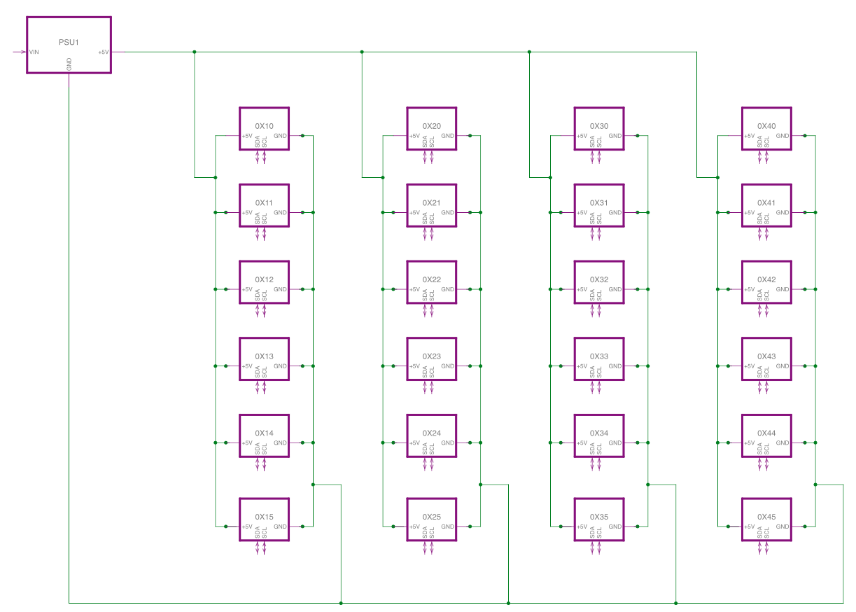
The circuit for each of the modules (0X10 etc.) is looking like this. Some notes about the different sections:

  • The two motors on the bottom right are connected to the ports PB and PD via darlington arrays
  • Connected to PC1/PC2 on the top right are two optical sensors for homing the stepper motors
  • PRG on the bottom is the programming port for the Atmega8

duostepper_RevC_schematic

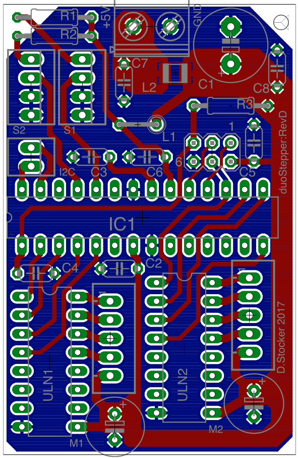
The PCB design (40 x 60 mm) I plan to order looks like this. This is not implemented, yet! duostepper_RevC_topbottom

duostepper_RevC_top

duostepper_RevC_bottom

UPDATE 2017-04-15:

I updated the power input section of the schematic with a beefier capacitor, additional 100nF-capacitors and a ferrite bead. I changed the motor-capacitors to 220µF as well.

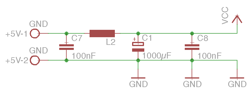
RevD_new_power_input

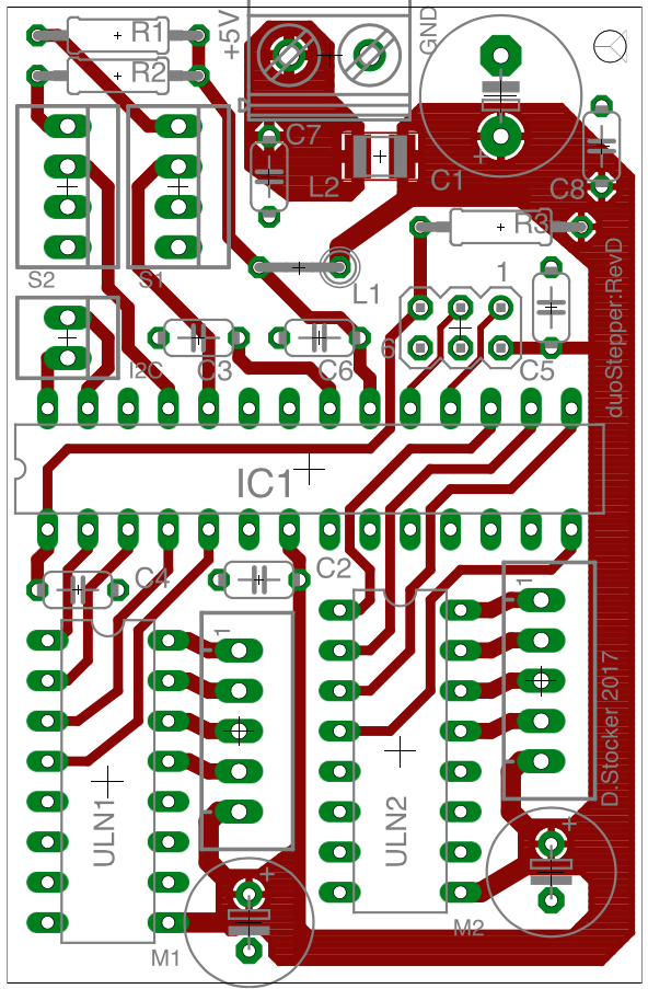
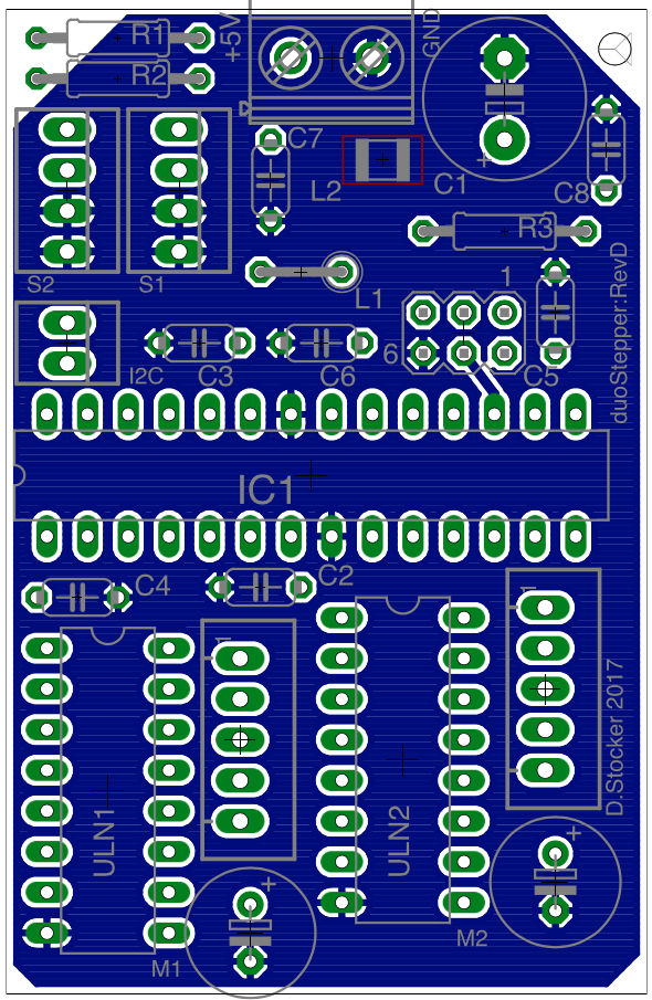
In the layout, I implemented it like this: duostepper_RevD_all duostepper_RevD_top duostepper_RevD_bottom

\$\endgroup\$
14
  • 1
    \$\begingroup\$ The "thick wires" have inductance. Approximately 1 microHenry per Meter. How long are the wires? Now, how fast are the currents being switched? (Use a scope to look at this). Then run this equation: Vbounce = Linductance * dI/dT. Consider example: 1uH (~ 1 meter) and 0.5 amps/ in 50 nanoseconds. Run the equation: V = 1e-6 * 1.0 amps/100nS, and the result: 1e-6 * 1e+7 ===== 10 volts. That is for ONE MOTOR. \$\endgroup\$ Commented Apr 12, 2017 at 17:45
  • 1
    \$\begingroup\$ @analogsystemsrf. That calculation makes no sense at all, the power line inductance is quite irrelevant. There are large (600 uF on DC input + 10 uF on the switches) capacitors on each board. If you want to suggest that the OP add say a 0.1 uF ceramic to each board that might be fair enough ....but you will not see 10 V transients on the power supply bus under any conditions. \$\endgroup\$ Commented Apr 12, 2017 at 17:53
  • 1
    \$\begingroup\$ So, what is your !2C bus length? (Physically). And what sort of cable are you using? Twisted pair? \$\endgroup\$ Commented Apr 12, 2017 at 18:21
  • 3
    \$\begingroup\$ In that case, what EXACTLY does "the Atmega8s are not working properly anymore" mean? If they are not driving the steppers as desired (which seems to be the criterion), how do you know the problem is not I2C related? Details, please. \$\endgroup\$ Commented Apr 13, 2017 at 4:49
  • 1
    \$\begingroup\$ Sounds reasonable. What gauge wire are you using for your power connections? And have you tried actually looking at your power supply output during failure with a scope? \$\endgroup\$ Commented Apr 13, 2017 at 13:25

3 Answers 3

2
\$\begingroup\$

The "thick wires" have less inductance than thin wires. 100:1 ratio is 1500nH/m while 50:1 ratio is 1000nH/m

  • Litz wire has much lower L and comes in many strands and AWG of enamel wire.

With all these stepper surge currents and dead-band half bridges, it will be a CM noise nightmare for any high L or C impedance coupling to stray input cables or tracks.

Recommendations

  • CM chokes on each pair to raise the CM impedance with optional shunt caps or ferrite beads for DM mode suppression. example SMD CM Choke 200mA <1ohm
  • Twisted pair cables, shielded, if bundled.
  • fault sense on open connections
  • Datum (aka Home/End Stop) opto Schmitt inverter sensor feedback on same CM choke twist pair for immunity. depending on cable length and arc noises nearby.
  • low ESR caps to shunt RdsOn/Coss current spikes
  • 0.5~1.5us Dead time depending on loads L/R ratios etc.
  • model your circuit design for EMI control including DCR, R distributed C on cables and cap ESR vs C
  • use accelerated pulse rates for slew control factoring Motor torque and inertial loads to obtain max speed and avoid skips or cogging at all costs.
  • include cogging current sensors in case of unexpected stiction
  • slots are generally efficient EMI antenna and bad if rise times << 50ns nearby

(Disclaimer) This is by no means a complete DFM list of recommendations

\$\endgroup\$
12
  • 1
    \$\begingroup\$ @Tony Where will all these stepper motor surge currents (that you want to add inductance to stop) come from? The stepper motor windings are an inductor, the current ramps up from zero doesn't it? You do have to take care in a 5/6 wire configuration that you have deadband between switches, but that is all. When you turn off the current in a winding there is a diode in the LN2003 that catches the inductive decay, but that current is local to the motor wiring so not reflected into the supply. \$\endgroup\$ Commented Apr 14, 2017 at 15:58
  • 1
    \$\begingroup\$ Stepper drivers must be controlled by DCM and not CCM thus deadtime current switches from Active device to Active device going thru a high Z transition. dI/dt emits EMI CM and DM noise controlled by loop area. so all commercial systems I have used like for PCB assembly automation use CM torroids on every stepper cable. I have many more examples. Laptop chargers, VGa cables, welders. Ignore this insight and next he will be asking about EMI issues.pAnasonic SMT CM chokes cost about 0.30$ in 100pc \$\endgroup\$
    – D.A.S.
    Commented Apr 14, 2017 at 16:08
  • 1
    \$\begingroup\$ @Tony. I don't disagree about EMI, but the issue at hand is unlikely in the extreme to be an EMI one. \$\endgroup\$ Commented Apr 14, 2017 at 16:20
  • 1
    \$\begingroup\$ Have you examined any of your EDM or CNC's with an AM Radio? then check for CM chokes in the design. \$\endgroup\$
    – D.A.S.
    Commented Apr 14, 2017 at 17:27
  • 1
    \$\begingroup\$ @TonyStewart.EEsince'75 ....I agree EMI can be a problem, I don't disagree that a commercial product needs to take EMI into account. However, do you think EMI is what's causing the problem in the question? I certainly don't. By the way EDM is nowhere near as noisy as one might imagine providing (and most EDM is) it's done underwater. Try dry point EDM (I have used it to cut miniature shapes out of feeler gauges), now that kicks up a real broad spectrum racket. But it doesn't crash my PC or cause my stepper motors (controllers) to stutter or lose origin. \$\endgroup\$ Commented Apr 15, 2017 at 0:25
2
\$\begingroup\$

I'd suggest the problems you are having have nothing to do with wire resistance, impedance or inductance. You have plenty of distributed capacitance throughout the system.

IMO the most likely problem is your I2C interface.
You show no pullups on the far end of your star connected buses, and I assume you are driving them all simultaneously from one master.
In addition any voltage drop that does occur in your high current ground wires is injected into the I2C signal for each board.

This NXP document might help you (particularly notice the three wire nature with twisted pair wiring).

To test out you system I'd suggest you initially write some test code for your ATMegas8's that does not use the I2C bus at all. Just do a continuous seek from end to end of your stepper motor travel. I'd predict that will work.
You can use an oscilloscope on your power supply wires and put to bed any thoughts of transients ....and measure your DC voltage at the far end of each star line to ensure you don't have too great a drop.

From there ...fix your I2C. Make sure you can address/control the boards on the end of the star lines and view you I2C signals for integrity.
I also notice you are using the internal RC clock for the ATMega's ...have you calibrated them?

You could also consider using an I2C multiplexor such as the PCA9547 to reduce the number of devices on your I2C master at any time.

Moving on ....when you seek advice with multiple questions not linked together it makes it hard to offer advice. The boards you are running on are from this question, and clearly don't have correct flood for power supply lines, have inadequate bypass capacitors and questionable connectors for the current flowing. It also mentions in the question the use of a breadboard to supply power, this cannot be done. Breadboards are not meant to pass large currents.

You also pointed out the power supply you are using in the comments (an important addition)

With the boards you are currently running I'd suggest the following (the new layout in this question looks much better by the way).

  1. Your power wiring needs to run direct from the power supply to the boards. 16 AWG wire seems quite adequate but getting two 16 AWG wires into your connector on a board may be a challenge.
    What I do for all my power supply (AC and DC) wiring in projects is use push in connectors such as this, they are readily available in 2-8 connection format and ideal for your 16 AWG wire; and you can get 20 A or 30 A ratings. These allow you to use only a single wire into your board power connector and if you pull straighten your wires make the wiring look nice.

  2. You need lots more capacitance on your boards....for the ones you have it's a bit late to do much, but you may be able to get better results from them. I'd suggest that you need about 1000 uf per board, and you could even put them on the connectors in item 1).

  3. A bit of a 'Hail Mary'. Raise your power supply to 5.4 VDC, this might just help ensure that the voltage dips on the boards are not enough to impact the ATMegas operation.

  4. As suggested before set your BODLEVEL=1 to get the lowest brownout detection level.

The new board layout looks much better.

\$\endgroup\$
5
  • 1
    \$\begingroup\$ Thank you for your pointers on improving the I2C-performance. However, I'm experiencing the stuttering-issues on the motors with the I2C completely turned off as well. My test-setup is just each ATMegas running its two motors nonstop. So I might run into some more I2C-related problems down the road, but so far this is the most stable part of the whole setup. \$\endgroup\$
    – dhst
    Commented Apr 13, 2017 at 4:17
  • 1
    \$\begingroup\$ @dhst Are you saying there is no I2C traffic when you are failing (stuttering)? \$\endgroup\$ Commented Apr 13, 2017 at 5:14
  • \$\begingroup\$ Yes, the I2C-bus is physically disconnected and I can still reproduce the stuttering of the motors. \$\endgroup\$
    – dhst
    Commented Apr 13, 2017 at 14:19
  • 1
    \$\begingroup\$ What interrupts are enabled(firing) when you test without I2C? \$\endgroup\$ Commented Apr 13, 2017 at 15:37
  • \$\begingroup\$ Just the Timer0-interrupt of the ATMega8 for running the two stepper motors. The code is mostly based on this library. I tried out different implementations, but the jittering remained the same. \$\endgroup\$
    – dhst
    Commented Apr 13, 2017 at 15:49
1
\$\begingroup\$

I think the most important phrase in your question is-

"The main issue that the Atmega8s are not working properly anymore when I run more than 5 of the motor-control-modules simultaneously."

Motors create a ton of noise at all different frequencies. This happens because, as the motor windings commutate, the create delta pulses which are extremely short (t -> 0) and high voltage (v -> ∞). Their noise spectrum is theoretically infinite. (Yes, I know to be truly infinite you can have only one pulse)

Because the motors generate a significant amount of noise at very high frequencies, everything on your PCB that is innocuous at low frequencies now begins to have an appreciable effect on your circuit. Capacitance between traces allows crosstalk to occur, and inductance causes currents to take unexpected paths back to ground. For what its worth, I'd guess your problem is from conducted noise back onto the power supply and not coupled noise. In other words, the motor noise is finding its way back onto the power supply, poisoning the microcontrollers.

Just some random questions:

  • Do the microcontrollers just stop working in some random part of the code, or the same place every time?

  • Could it be a problem with the the optical sensors causing the code to work unexpectedly?

  • Is it always at some exact number of motors that the problem shows up? Can you get 6 to work if you run just the right selection of motors? Does motor speed matter?

  • Is it possible to provide separate digital and analog power to each module?

My guess is you have only a couple of things wrong with your board. But just like hunting Easter eggs, you may find the problem right away, or it may take a while and require a lot of learning.

It may be more than you bargained for, but Electromatic Compatibility by Henry Ott, especially chapter 3 on grounding, is a great resource for understanding your problem. Ground is hardly ever at 0 volts, which is extremly confusing at first. But Mr. Ott does a great job of making it much more understandable.

Hope this helps.

\$\endgroup\$

Your Answer

By clicking “Post Your Answer”, you agree to our terms of service and acknowledge you have read our privacy policy.

Not the answer you're looking for? Browse other questions tagged or ask your own question.